Dust removing device for electric automation equipment

A technology of electrical automation and dust removal device, which is applied in the direction of cleaning method using gas flow, removing smoke and dust, and cleaning method using tools, etc., which can solve problems such as easy dust accumulation, blockage of heat dissipation holes of heat dissipation plate, and influence on equipment service life, etc., to achieve Improve dust removal efficiency, avoid breakage, and avoid damage

Active Publication Date: 2020-02-07
ZHUHAI HENGQIN KUNPENG NEW ENERGY ENVIRONMENTAL PROTECTION TECH CO LTD
View PDF7 Cites 5 Cited by
  • Summary
  • Abstract
  • Description
  • Claims
  • Application Information

AI Technical Summary

Problems solved by technology

[0003] The purpose of the present invention is to provide a dust removal device for electrical automation equipment to solve the problem that during the use of electrical automation equipment, because the electrical automation equipment is in a static state for a long time, the internal electrical components are prone to generate static electricity, so that the position of the heat dissipation plate of the electrical automation equipment is easy. Dust accumulation, long-term accumulation of a large amount of dust will easily lead to blockage of the heat dissipation holes distributed on the heat dissipation plate, which is not conducive to the timely heat dissipation of electrical components, and then makes the inside of the electrical automation equipment easy to overheat and affect the service life of the equipment; the existing dust removal device is mainly composed of a drive mechanism and The rolling brush is composed of a rolling brush. When the rolling brush is rotating, it can only treat the dust on the surface of the equipment, and there is no recovery mechanism for the removed dust. During long-term treatment, dust is easy to accumulate inside the dust removal device, which affects the dust removal efficiency of the dust removal device. Technical problem

Method used


Image

  • Dust removing device for electric automation equipment
  • Dust removing device for electric automation equipment
  • Dust removing device for electric automation equipment

Examples


Embodiment Construction

[0029] The technical solutions of the present invention will be clearly and completely described below in conjunction with the embodiments. Apparently, the described embodiments are only some of the embodiments of the present invention, not all of them. Based on the embodiments of the present invention, all other embodiments obtained by persons of ordinary skill in the art without creative efforts fall within the protection scope of the present invention.

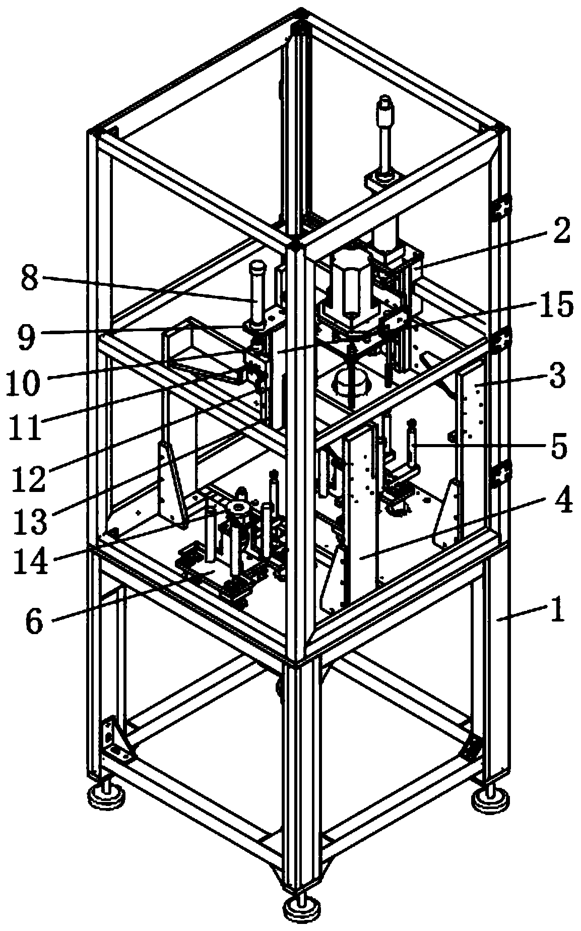
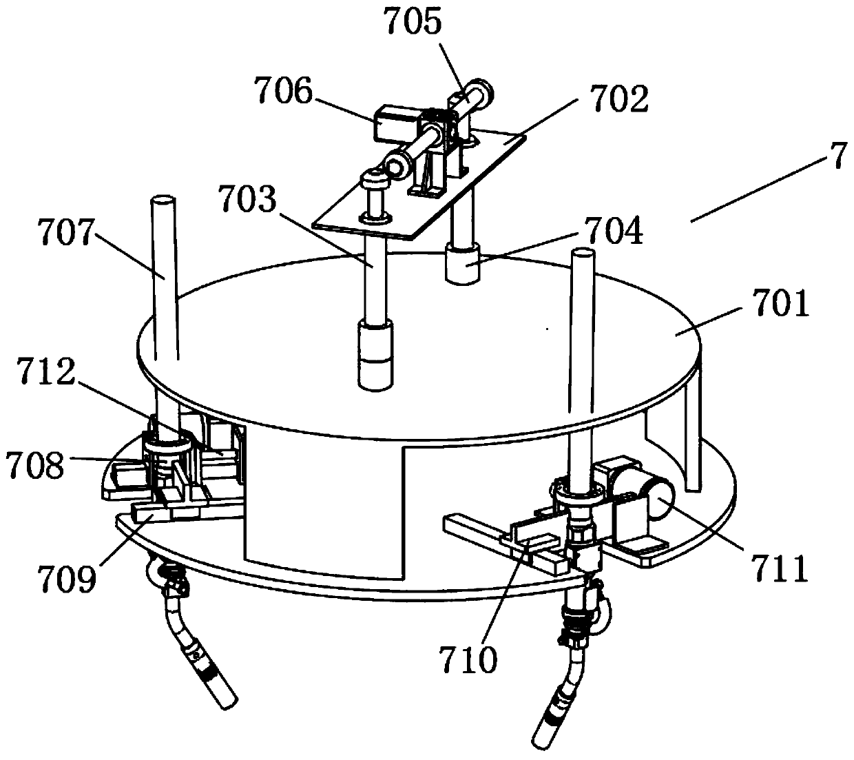
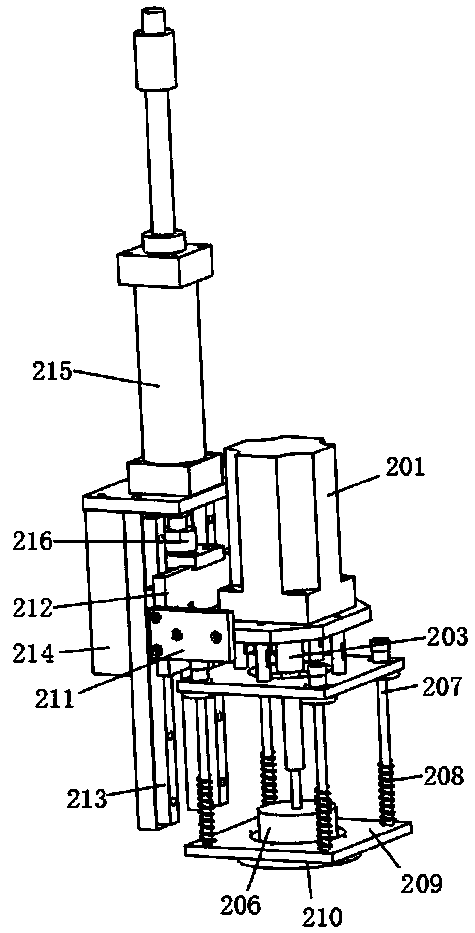
[0030] see Figure 1-5, a dust removal device for electrical automation equipment, including: a cleaning mechanism 2 for cleaning dust, a dust blowing mechanism 7 located at one end of the cleaning mechanism 2 to further clean the surface grooves of the electrical automation equipment, and a dust blowing mechanism 7 located at the cleaning mechanism 2 and The bottom end of the dust blowing mechanism 7 is used for the suction cup 14 to recycle the dust, wherein the dust blowing mechanism 7 is fixedly connected with the limit...


PUM


Abstract

The invention discloses a dust removing device for electric automation equipment. A rotating rod is driven to rotate by a second motor, and a supporting disc is driven to move in the length directionof a screw rod, so that guide pipes move in the vertical direction to perform dust blowing treatment on different areas of the electric automation equipment, and the dust removing efficiency is improved; and when a third cylinder is started, and the third cylinder pushes a third push rod to move, so that the guide pipes move back and forth in a movable groove and are contracted or extended in thediameter direction of a supporting plate, and then the dust blowing range of the guide pipes is changed; and the working positions of the guide pipes can be flexibly changed according to different shapes of the electric automation equipment, so that the guide pipes carry out comprehensive dust removing treatment on the electric automation equipment, and the conditions that heat dissipation holes distributed on a heat dissipation plate are prone to be blocked caused by accumulation of a large amount of dust for a long time, then blockage is not favorable for timely heat dissipation of electricelements, and therefore, the internal part of the electric automation equipment is prone to overheating to influence the service life of the equipment are avoided.

Description

technical field [0001] The invention relates to the field of dust removal, in particular to a dust removal device for electrical automation equipment, and belongs to the technical field of application of the dust removal device for automation equipment. Background technique [0002] Electrical equipment is a general term for generators, transformers, power lines, circuit breakers and other equipment in the power system, and electrical equipment is a general term for generators, transformers, power lines, circuit breakers and other equipment in the power system. During use, due to the long-term static state, the internal electrical components are prone to static electricity, which makes the position of the heat sink of the electrical automation equipment easy to accumulate dust. Long-term accumulation of a large amount of dust will easily lead to blockage of the heat dissipation holes distributed on the heat sink, which is not conducive to the maintenance of electrical compone...

Claims


Application Information

Patent Timeline
Patent Type & Authority Applications(China)
IPC IPC(8): B08B5/02B08B1/04B08B15/04B08B13/00
CPCB08B1/04B08B5/02B08B13/00B08B15/04
Inventor 潘建
Owner ZHUHAI HENGQIN KUNPENG NEW ENERGY ENVIRONMENTAL PROTECTION TECH CO LTD
Why Eureka
Try Eureka