Supercharge Your Innovation With Domain-Expert AI Agents!

Transmission shaft forging forming process and forging die

A forming process and transmission shaft technology, applied in the field of forging, can solve the problems of high energy consumption, large consumption of materials, and increased projection area, etc.

Pending Publication Date: 2020-02-07
湖南高致精工机械有限公司
View PDF0 Cites 0 Cited by
  • Summary
  • Abstract
  • Description
  • Claims
  • Application Information

AI Technical Summary

Problems solved by technology

The above-mentioned forging method has the following disadvantages: ① The projected area of ​​the forging in the parting direction doubles, and the equipment required for forming is large in tonnage and consumes a lot of energy; ② It consumes a lot of materials, especially at the opening of the fork.

Method used


Image

  • Transmission shaft forging forming process and forging die
  • Transmission shaft forging forming process and forging die
  • Transmission shaft forging forming process and forging die

Examples


Embodiment 1

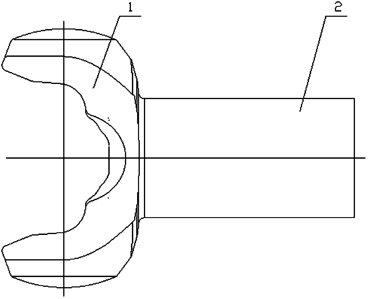
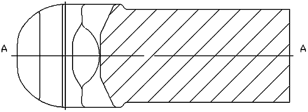
[0026] A transmission shaft forging forming process, which includes the following processing steps: blanking - heating - heading - forging - trimming - heat treatment, using small-sized bars for blanking, and upper and lower forging. Die vertical forging, such as image 3 As shown, the transmission shaft forging is formed by connecting the fork 1 and the rod 2. The parting surface of the transmission shaft forging is a curve designed according to the shape of the fork, and the parting surface is composed of B1-B2-B3-B4 -The six points of B5-B6 are connected to form a curve, and the parting surface can divide the fork head into upper and lower parts.

[0027] Adopting the above-mentioned technical scheme, because the small-sized bar is used for processing, and the parting surface is designed based on the fork head, and the vertical forging is used instead, the production efficiency is improved, the deficiency of the existing technology is overcome, and the forming force of the ...

Embodiment 2

[0029] A transmission shaft forging die, the transmission shaft is formed by connecting a fork and a rod, such as Figure 4 , 5 As shown, the forging die includes an upper die 3 and a lower die 4, the die surface of the lower die 4 is provided with a cavity 4a adapted to the shape of the outer surface of the drive shaft yoke and bridges on the left and right sides of the cavity 4a part 4b, the bridge part 4b communicates with the cavity 4a; a through hole 4c is provided downward in the center of the bottom of the cavity 4a, and the aperture of the through hole 4c gradually becomes smaller from top to bottom; the mold surface of the upper mold 3 is provided with A downward protruding punch 3a, the structure of the punch 3a is adapted to the shape of the inner surface of the transmission shaft yoke, the mold surface of the upper die 3 is respectively provided with a groove 3b on the left and right sides of the punch 3a, and the left and right sides The grooves 3b are symmetrica...


PUM


Abstract

The invention discloses a transmission shaft forging forming process. A transmission shaft forging is formed by connecting a fork head and a rod part. During forging forming, an upper die and a lowerdie are adopted for vertical forging. A parting surface of the transmission shaft forging is a curve designed according to the shape of the fork head and can divide the fork head into an upper portionand a lower portion. The invention further provides a transmission shaft forging die. The transmission shaft forging die comprises the upper die and the lower die. A cavity matched with the outer surface of the transmission shaft fork head in shape is formed in a die surface of the lower die. A through hole is downwards formed in the center of the bottom of the cavity. A punch protruding downwards is arranged on a die surface of the upper die. The structure of the punch is matched with the shape of the inner surface of the transmission shaft fork head. The portions, on the left side and rightside of the punch, of the die surface of the upper die are each provided with a groove. The grooves in the left side and the right side are symmetrical and matched with the cavity of the lower die insize. In this way, an upper prong of the fork head is partially arranged on the upper die, and the lower portion of the fork head and the rod part are arranged on the lower die.

Description

technical field [0001] The invention relates to the technical field of forging, in particular to a forming process for a transmission shaft forging and a transmission shaft forging die. Background technique [0002] figure 1 The transmission shaft shown is an important security part on the vehicle, and it is formed by connecting the fork head 1 and the rod part 2. Its function is to transmit the rotational torque of the engine to each component, and it itself bears a huge transmission force during the transmission process. And alternating torque, so the overall mechanical performance requirements are high. The traditional forging method of the drive shaft: 1) The process is: blanking - heating - pulling out the long rod part - forging forming - trimming - heat treatment, the billet is made of large-size bar material heated and then drawn out and rolled thin rod part; 2) Design the parting surface of the forging to be an axial straight line (see figure 2 The A-A line), th...

Claims


Application Information

Patent Timeline
Patent Type & Authority Applications(China)
IPC IPC(8): B21K1/12B21J13/02
CPCB21K1/12B21J13/02
Inventor 刘钧沈运海蒲焕章沈祁阳汤桥平
Owner 湖南高致精工机械有限公司
Features
  • R&D
  • Intellectual Property
  • Life Sciences
  • Materials
  • Tech Scout
  • Unparalleled Data Quality
  • Higher Quality Content
  • 60% Fewer Hallucinations
Learn More