
Optical element switching device and image recording device having same

A technology of optical components and switching devices, applied in the direction of optical components, optical, electrical components, etc., can solve the problems of affecting the shooting effect, optical components deviate from the predetermined position, and increase the burden, so as to improve the shooting accuracy and ensure the shooting effect

Pending Publication Date: 2020-02-11
曹广德
View PDF0 Cites 2 Cited by
  • Summary
  • Abstract
  • Description
  • Claims
  • Application Information

AI Technical Summary

Problems solved by technology

Although you can get a good shooting effect in this way, carrying various lenses with you will greatly increase the burden of travel.
At the same time, it takes a certain amount of time to change the lens, but sometimes the opportunity to shoot is fleeting, and the best time to shoot after the lens change is completed has been missed, leaving only regret
However, portable small cameras are currently fixed with a lens on the body, which cannot be replaced. Although it is convenient to carry, when encountering different shooting scene requirements in the actual use process, it is difficult to achieve comparison with only one lens. Satisfactory effect
[0004] For this reason, a rotating mechanism equipped with multiple optical elements has been used to rotate under the driving device, and stop rotating after reaching a predetermined position, and carry out corresponding shooting schemes. However, after the rotating mechanism reaches the predetermined position, due to the position of the rotating mechanism is not Fixed, when it is subjected to external force, it may cause the optical element in the current use state to deviate from the predetermined position, affecting the shooting effect

Method used


Image

  • Optical element switching device and image recording device having same
  • Optical element switching device and image recording device having same
  • Optical element switching device and image recording device having same

Examples


Embodiment Construction

[0033] The technical solutions of the present invention will be clearly and completely described below in conjunction with the accompanying drawings; obviously; the described embodiments are part of the embodiments of the present invention; not all of them. Based on the embodiments of the present invention; all other embodiments obtained by persons of ordinary skill in the art without creative work; all belong to the protection scope of the present invention.

[0034] In addition; the technical features involved in the different embodiments of the present invention described below can be combined with each other as long as they do not constitute a conflict with each other.

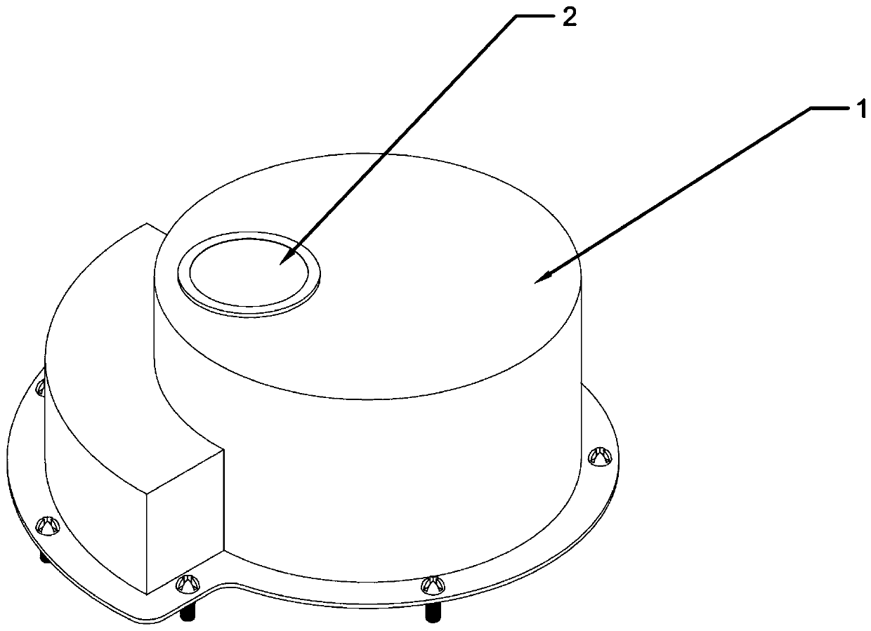
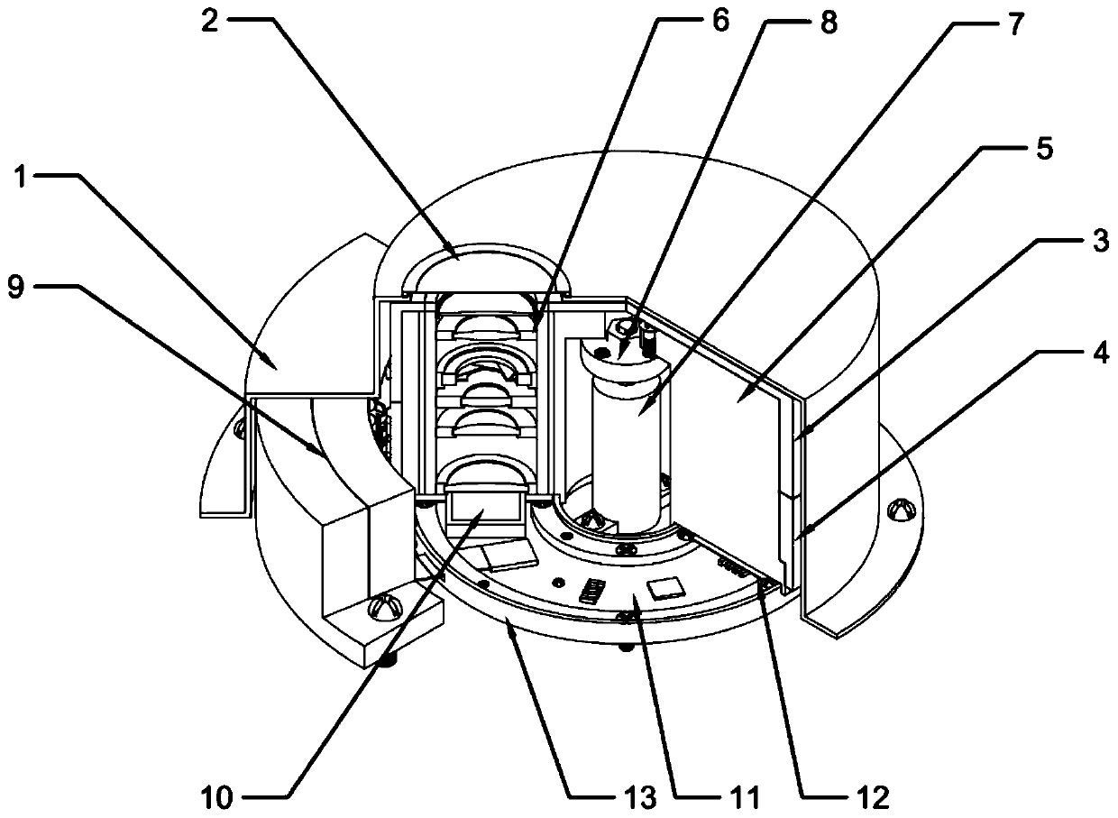
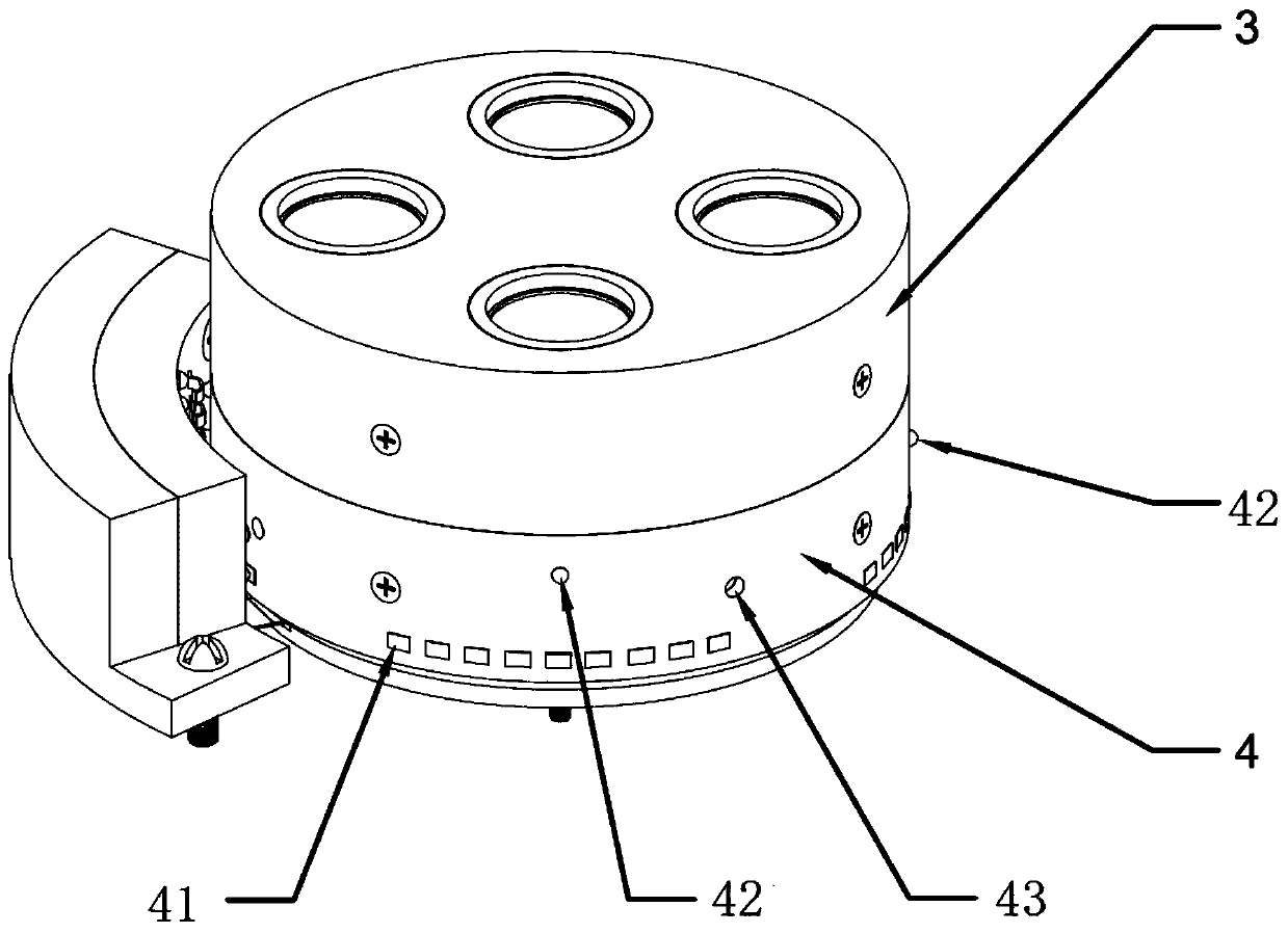
[0035] Such as Figure 1-5 As shown, an optical element switching device provided by the present invention includes: a base 5, a plurality of optical elements 6 are arranged on the end surface facing the glass window 2; a driving mechanism 7 is connected with the base 5 for Drive the base 5 to rotate to t...


PUM


Abstract

The present invention relates to the technical field of optical instruments, and in particular, to an optical element switching device and an image recording device having the same. The optical element switching device includes: a base where a plurality of optical elements are arranged on an end surface facing a glass window; a driving mechanism connected to the base and used for driving the baseto rotate to transport the optical elements to predetermined positions; a positioning mechanism connected to the base and having a first state in which the positioning mechanism is locked to the basewhen the optical elements rotate to the predetermined positions, and a second state in which the positioning mechanism is unlocked from the base when the driving mechanism drives the base to rotate. The invention provides the optical element switching device capable of fixing the positions of the switched optical elements so as to improve a capture effect, and an image recording device having thesame.

Description

technical field [0001] The invention relates to the technical field of optical instruments and equipment, in particular to an optical element switching device and an image recording device having the same. Background technique [0002] A camera is a device that uses the principle of optical imaging to form an image and uses a film to record the image. It is an optical device used for photography. In modern social life, there are many devices that can record images, and they all have the characteristics of cameras, such as medical imaging equipment, astronomical observation equipment, etc. [0003] At present, in order to meet the photography needs of different scenes, SLR cameras and mirrorless cameras, which are high-end photography needs, need to be equipped with lenses of different focal lengths. Although good shooting results can be obtained in this way, carrying various lenses with you will greatly increase the burden of travel. At the same time, it takes a certain am...

Claims


Application Information

Patent Timeline
IPC IPC(8): G03B17/14G02B7/16H04N5/225
CPCG03B17/14G02B7/16H04N23/55
Inventor 曹广德
Owner 曹广德
Learn More