
Method and control system for monitoring automation system

A technology of automation system and control system, which is applied in the field of automation system, can solve the problems of image display size limitation, difficult user, heavy burden, etc., and achieve the effects of flexible and complete reproduction, intuitive navigation, and easy recognition

Active Publication Date: 2022-03-29
因智克富勘软件技术有限公司
View PDF10 Cites 0 Cited by
  • Summary
  • Abstract
  • Description
  • Claims
  • Application Information

AI Technical Summary

Problems solved by technology

However, in the area of ​​the control stations of automation systems, the problem arises that the information density to be displayed is extremely high, but on the other hand the display size of the images is limited, especially when using mobile display units
Especially in larger installations it is difficult on the one hand to present all information to the user and on the other hand it is difficult not to burden the user with potentially useless information for the purpose at hand
Proportionally correct three-dimensional representations also pose a problem: the view of the currently relevant component to the user can be confused with other components

Method used


Image

  • Method and control system for monitoring automation system
  • Method and control system for monitoring automation system
  • Method and control system for monitoring automation system

Examples


Embodiment Construction

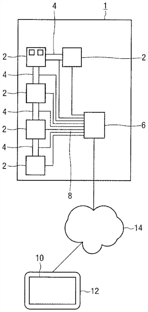
[0039] figure 1 An automated plant 1 is schematically represented, ie an industrial plant in which production steps and processing steps are automated. The industrial plant comprises a large number of components, including a processing station 2 to which the product to be processed or its primary table is transported. This is done by means of conveying means 4, such as conveyor belts.

[0040] The control and monitoring of the automation plant 1 is carried out in the control system 6 , the processing sequence is monitored and, if necessary, influenced by corresponding data from the automation plant 1 with the cooperation of the user. For this purpose, the control system 6 has one or more devices or data connections to devices on the various components 2, components 4 of the automation system 1 for measurement, adjustment, control, display, alarm, recording, exchange or calculation Item 8.

[0041] In the embodiment designed as a screen on the mobile unit 12 , the display of...


PUM


Abstract

The present invention provides a method for monitoring an automated system comprising a plurality of components, comprising: rendering, by a processor, an image from a three-dimensional scene representing at least part of an automated system based on position data and viewing direction data; and displaying on a display unit image. The method makes it possible to monitor an automation system on a relatively small display device, displaying all relevant information simultaneously. To this end, the components are distributed on the base plates of the automation system, and the components are respectively arranged in a three-dimensional scene on one of the base plates, and input elements associated with the base plates are provided, wherein the vertical distance between two adjacent base plates in the three-dimensional scene The distance depends on the input changes at the input elements, and the material paths between the components of the automation system are represented as lines in the scene, where at least one line represents the material path between adjacent base plates, and where when two in the three-dimensional scene As the vertical distance between adjacent base plates changes, the length of the line changes accordingly.

Description

technical field [0001] The invention relates to a method for monitoring an automation system having a plurality of components, comprising: rendering, by a processor, an image from a three-dimensional scene representing at least a part of the automation system based on position data and viewing direction data; and displaying on a display unit the image. The invention also relates to a computer program product and a control system. Background technique [0002] Automated systems are industrial equipment in which production and processing steps are fully or partially automated. Depending on the type of product being manufactured or processed, automation systems can be highly individually designed. Usually, however, an automated system consists of processing stations to which the products to be processed or their primary tables are transported in a certain sequence by means of a conveyor system and where they are processed. The conveying system comprises various well-known co...

Claims


Application Information

Patent Timeline
Patent Type & Authority Patents(China)
IPC IPC(8): G05B19/418
CPCG05B19/41885G05B2219/32339G05B23/0216G06T19/20G05B19/41845G05B23/024
Inventor 乌瑞琪·欧克斯汤玛斯·斯图姆菲格法比恩·豪斯勒
Owner 因智克富勘软件技术有限公司
Learn More