
Terminal crimping device and terminal crimping method

一种端子压接、压接位置的技术,应用在连接、电气元件、电路等方向,达到抑制移位的效果

Active Publication Date: 2020-02-14
YAZAKI CORP +1
View PDF7 Cites 4 Cited by
  • Summary
  • Abstract
  • Description
  • Claims
  • Application Information

AI Technical Summary

Problems solved by technology

In the technology described in Patent Document 1, the terminal interval in the terminal joint body is wider than the interval of the electric wires at the crimping position

Method used


Image

  • Terminal crimping device and terminal crimping method
  • Terminal crimping device and terminal crimping method
  • Terminal crimping device and terminal crimping method

Examples


Embodiment Construction

[0056] Hereinafter, embodiments of the present invention will be described.

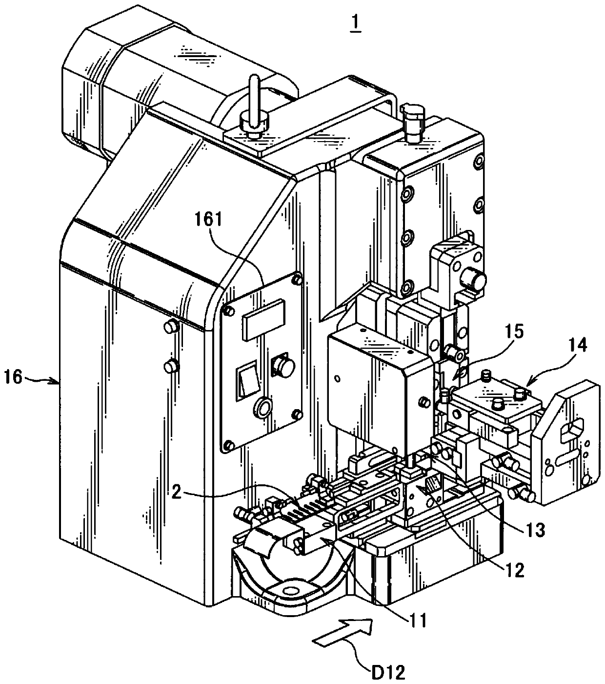
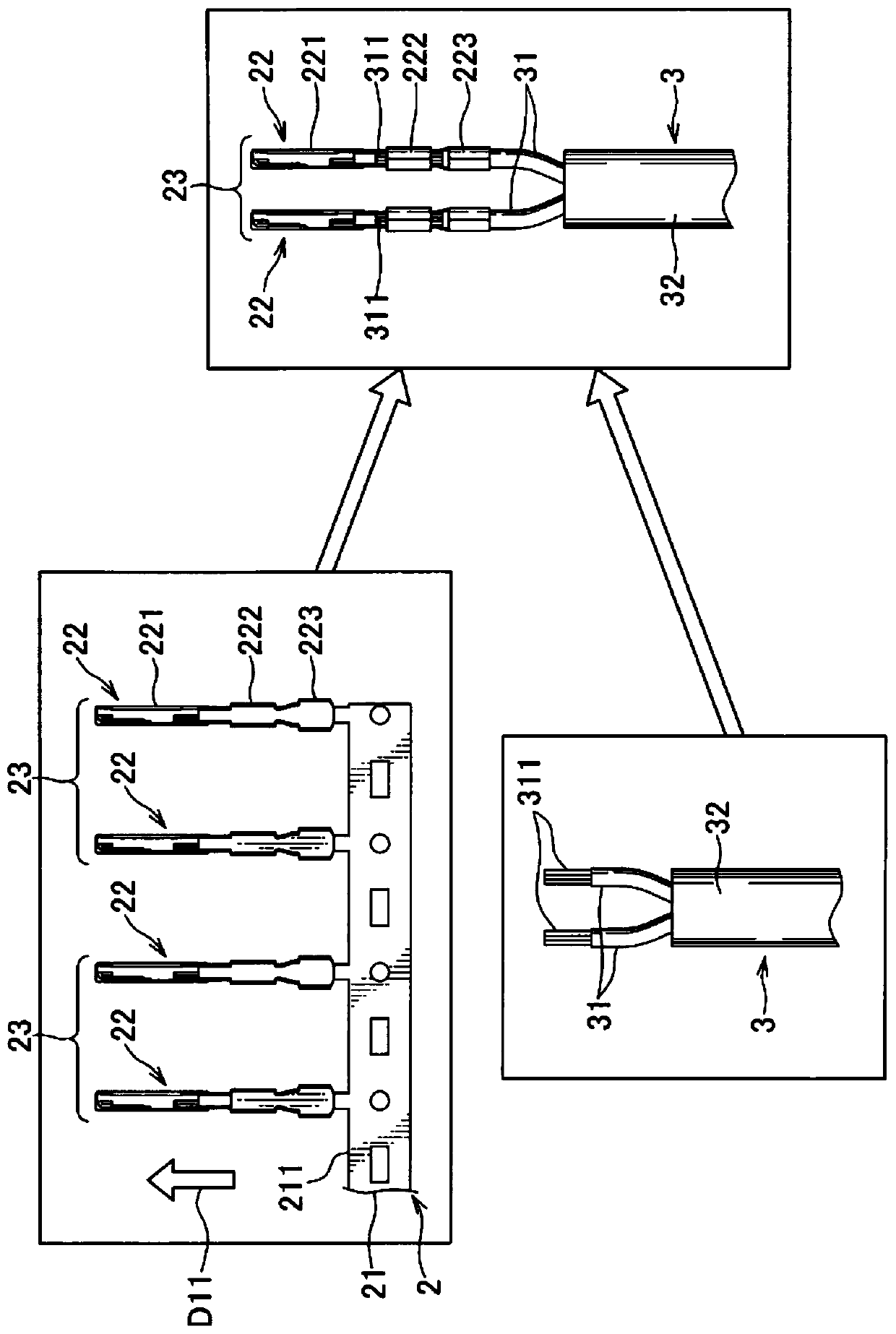
[0057] figure 1 is a view showing a terminal crimping device according to an embodiment of the present invention. and, figure 2 is shown by figure 1 Schematic representation of the steps performed by the terminal crimping apparatus shown.

[0058] The terminal crimping device 1 in the present embodiment is a device that crimp-connects the respective terminals 22 of the terminal coupling body 2 in which the plurality of terminals 22 are coupled by the carrier 21 to the crimping positions of the multi-core cable 3 at predetermined intervals A pair of covered wires 31 (electric wires) arranged.

[0059] In the present embodiment, the multi-core cable 3 is a two-core cable, and a pair of covered wires 31 are covered by an insulating sheath 32 . The insulating sheath 32 at one end of the multi-core cable 3 is removed and the covered electric wire 31 is exposed, and the covering of the end of each of...


PUM


Abstract

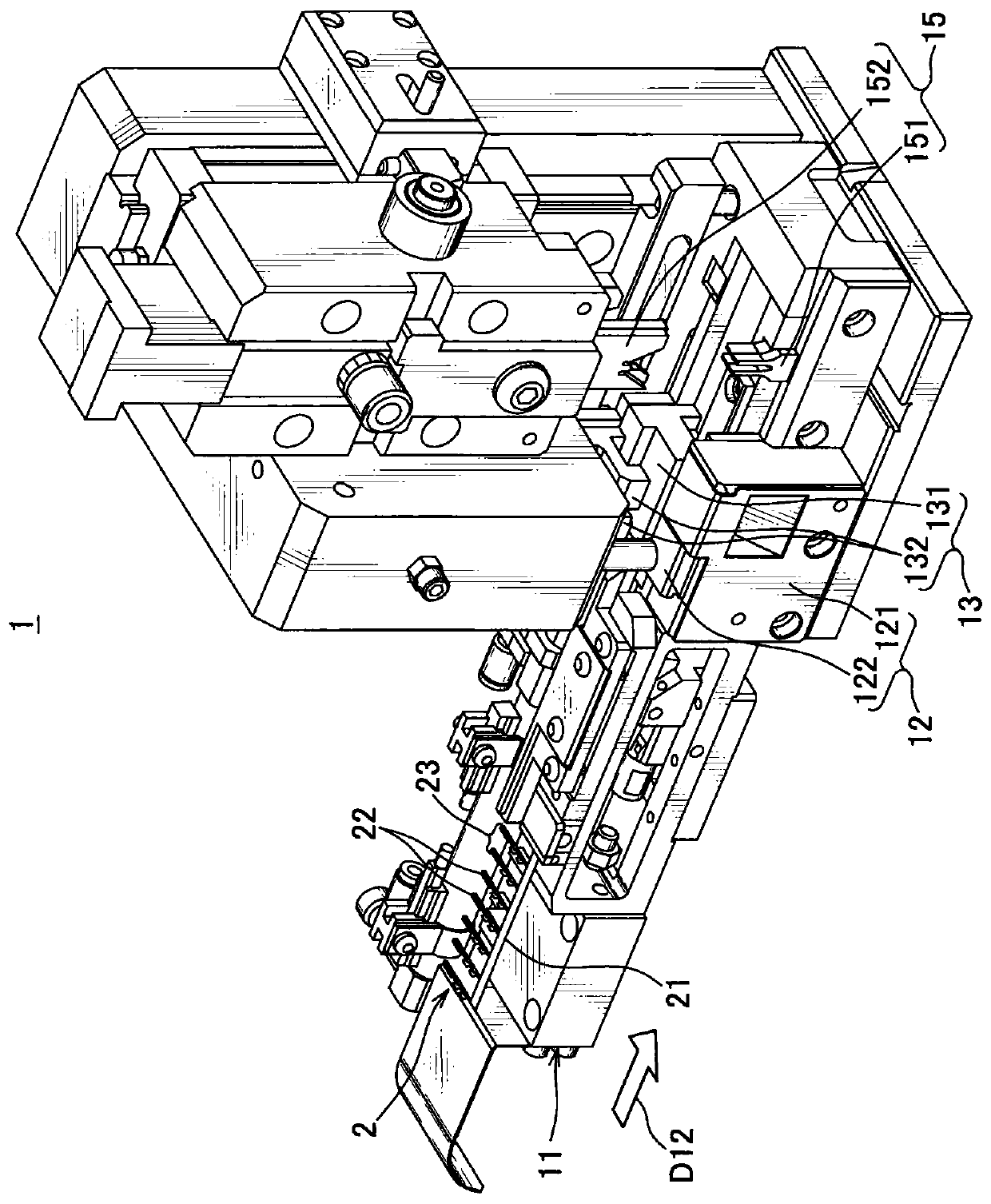
A terminal crimping device and a terminal crimping method are provided that collectively crimp-connect a terminal to an electric wire while suppressing displacement of the terminal at a crimp position. The terminal crimping device 1 includes a cutting part 12 configured to cut from the carrier 21 each of the two or more terminals belonging to one terminal set at one end side in the terminal coupled body 2; a terminal conveyance part 13 configured to convey the two or more terminals cut at the cutting part 12 to a crimp position corresponding to the predetermined interval while adjusting a terminal interval of the two or more terminals 22 to an arrangement interval of the covered electric wire 31 at the crimp position in a conveyance direction D12 (longitudinal direction) of the terminal coupled body 2; and a crimping part 15 configured to collectively crimp-connect the two or more terminals 22, conveyed to the crimp position, to the electric wire 31.

Description

technical field [0001] The present invention relates to a terminal crimping device and a terminal crimping method for crimping and connecting each terminal of a terminal coupling body to an electric wire in which a plurality of terminals pass through With plate carrier connection. Background technique [0002] Conventionally, a technique is known in which a terminal coupling body in which a plurality of terminals are joined by a tape-shaped carrier is supplied as a material, and the respective terminals in the terminal coupling body are crimp-connected to electric wires (eg , see Patent Document 1). [0003] In the technique described in Patent Document 1, a plurality of terminals joined by a carrier are commonly crimp-connected to an electric wire. At this time, for example, the terminal interval in the terminal coupling body and the interval between the wires arranged in accordance with the terminal array and the like in the connector at the crimping position often do no...

Claims


Application Information

Patent Timeline
Patent Type & Authority Applications(China)
IPC IPC(8): H01R43/048H01R43/055
CPCH01R43/0482H01R43/055H01R43/052
Inventor 增田浩辅高桥雄治沼泽明哉
Owner YAZAKI CORP
Learn More