
Yarn winding device for textile

A winding device and yarn technology, applied in the direction of transportation and packaging, thin material handling, and delivery of filamentous materials, etc., can solve problems such as broken wires, affecting production efficiency, and difficult to find, so as to prevent idling, reduce production costs, The effect of increasing friction

Active Publication Date: 2021-07-16
安徽双盈纺织有限公司
View PDF12 Cites 0 Cited by
  • Summary
  • Abstract
  • Description
  • Claims
  • Application Information

AI Technical Summary

Problems solved by technology

[0002] Yarn is an important raw material for making gauze. Usually, the yarn purchased from the outside is raw material thread, which needs to be processed to make gauze. Driven by the world trend, the development of the yarn industry is also rapid. With the continuous demand With the improvement, the artificial labor force has been unable to keep up with the production demand, and the emerging machinery has also improved the production efficiency while reducing the labor workload; but in the yarn production process, the thread often breaks when the yarn is wound. , the yarn breaking device still continues to wind, and it is not easy to be found, which is very inconvenient and greatly affects the production efficiency. Therefore, a textile yarn winding device is designed and produced here to solve the above problems.

Method used


Image

  • Yarn winding device for textile
  • Yarn winding device for textile
  • Yarn winding device for textile

Examples


Embodiment 1

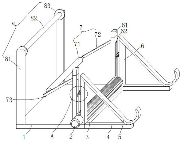
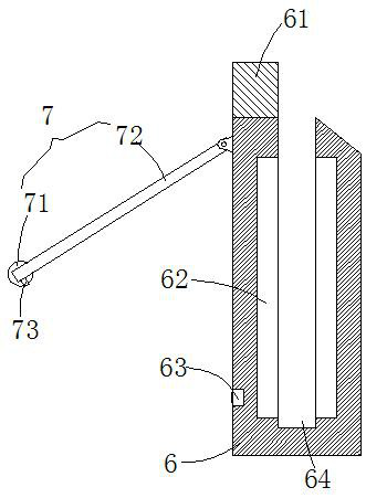
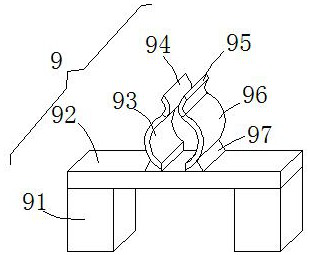
[0030] see Figure 1-5 , the present embodiment provides a yarn winding device for textiles, comprising a base 1 and two emergency stop mechanisms 9, the front and rear ends of the top surface of the base 1 are vertically welded with a support frame 6, and the left end of the front support frame 6 is A limit switch 63 is embedded in the bottom of the surface, and the signal output port of the limit switch 63 is connected with a data processing module 10, and a transmission roller 3 is arranged between the bottom of the opposite side wall of the two support frames 6, and the bottom of the front end of the front support frame 6 A motor 2 is provided, and the motor 2 runs through the side wall of the front side support frame 6 through the rotation of the power shaft, and is connected with the front end surface of the transmission roller 3. The middle positions of the two support frames 6 are provided with a rectangular placement gap 64, and the two rectangular placement gaps The ...

Embodiment 2

[0039] see Figure 1-5 , further improvements have been made on the basis of Example 1:


PUM


Abstract

The invention discloses a yarn winding device for textile, which comprises a base and two emergency stop mechanisms, a support frame is vertically welded at the front and rear ends of the top surface of the base, and a travel switch is embedded in the bottom of the left end surface of the front support frame. , the signal output port of the travel switch is connected with a data processing module, a transmission roller is installed between the bottom of the opposite side wall of the two support frames, and a motor is provided at the bottom of the front end of the front support frame, and the motor runs through the front support through the rotation of the power shaft The side wall of the frame is connected with the front end of the transmission roller. There are rectangular placement gaps in the middle of the two support frames. Limiting chutes are provided on the left and right sides of the inner cavity of the two rectangular placement gaps. The two emergency stop mechanisms are respectively Sliding clips are placed on both sides of the two rectangular placement gaps to limit the inner cavity of the chute. The invention is convenient to automatically unload the winding roller after the winding is completed, and reduces the production cost. In addition, after the yarn is broken, the winding can be stopped in time, so that the staff can find and deal with it in time, which is convenient and quick.

Description

technical field [0001] The invention relates to the technical field related to textiles, in particular to a yarn winding device for textiles. Background technique [0002] Yarn is an important raw material for making gauze. Usually, the yarn purchased from the outside is raw material thread, which needs to be processed to make gauze. Driven by the world trend, the development of the yarn industry is also rapid. With the continuous demand With the improvement, the artificial labor force has been unable to keep up with the production demand, and the emerging machinery has also improved the production efficiency while reducing the labor workload; but in the yarn production process, the thread often breaks when the yarn is wound. , The broken yarn device still continues to wind up and is not easy to be found. This is very inconvenient and greatly affects production efficiency. Therefore, a yarn winding device for textiles is designed and produced here to solve the above problems...

Claims


Application Information

Patent Timeline
Patent Type & Authority Patents(China)
IPC IPC(8): B65H57/14B65H63/036B65H54/42B65H63/08B65H67/04
CPCB65H54/42B65H57/14B65H63/036B65H63/082B65H67/0411B65H2701/31
Inventor 刘化杰刘云雷李小辉
Owner 安徽双盈纺织有限公司
Learn More