
Water-saving type water supply and drainage device

A water supply and drainage, water-saving technology, applied in the field of water-saving water supply and drainage devices, can solve problems such as blockage, and achieve the effects of avoiding blockage, good water quality, and novel structure

Inactive Publication Date: 2020-11-13
南京迈科拓信息科技有限公司
View PDF1 Cites 0 Cited by
  • Summary
  • Abstract
  • Description
  • Claims
  • Application Information

AI Technical Summary

Problems solved by technology

[0004] Based on the technical problem that the existing water supply and drainage device is easy to cause blockage when dealing with the filamentous garbage deposited on the bottom of the pool, the present invention proposes a water-saving water supply and drainage device

Method used


Image

  • Water-saving type water supply and drainage device
  • Water-saving type water supply and drainage device
  • Water-saving type water supply and drainage device

Examples


Embodiment 1

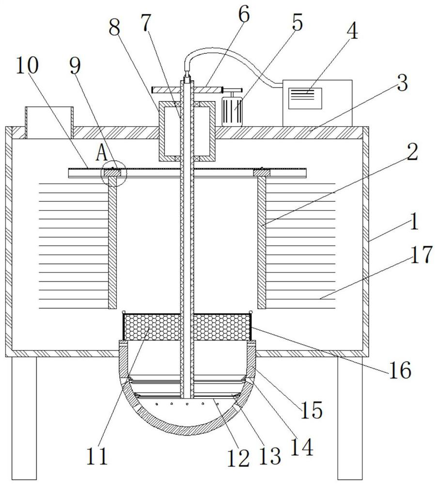
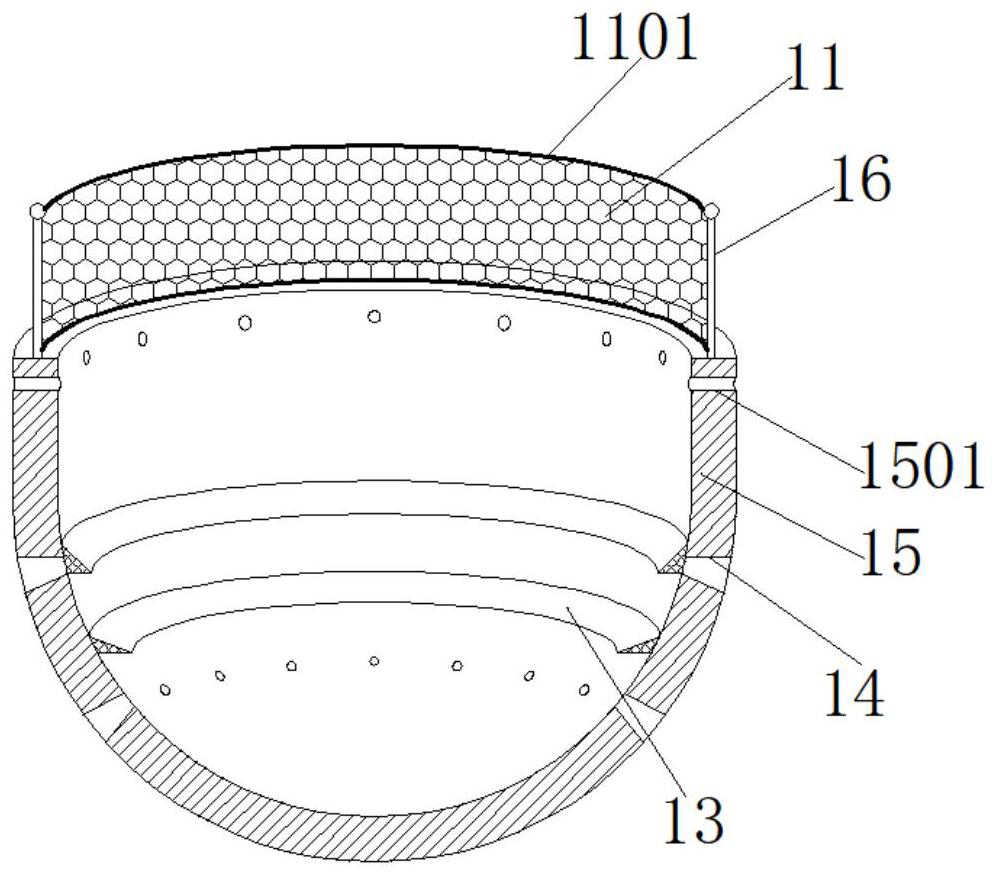
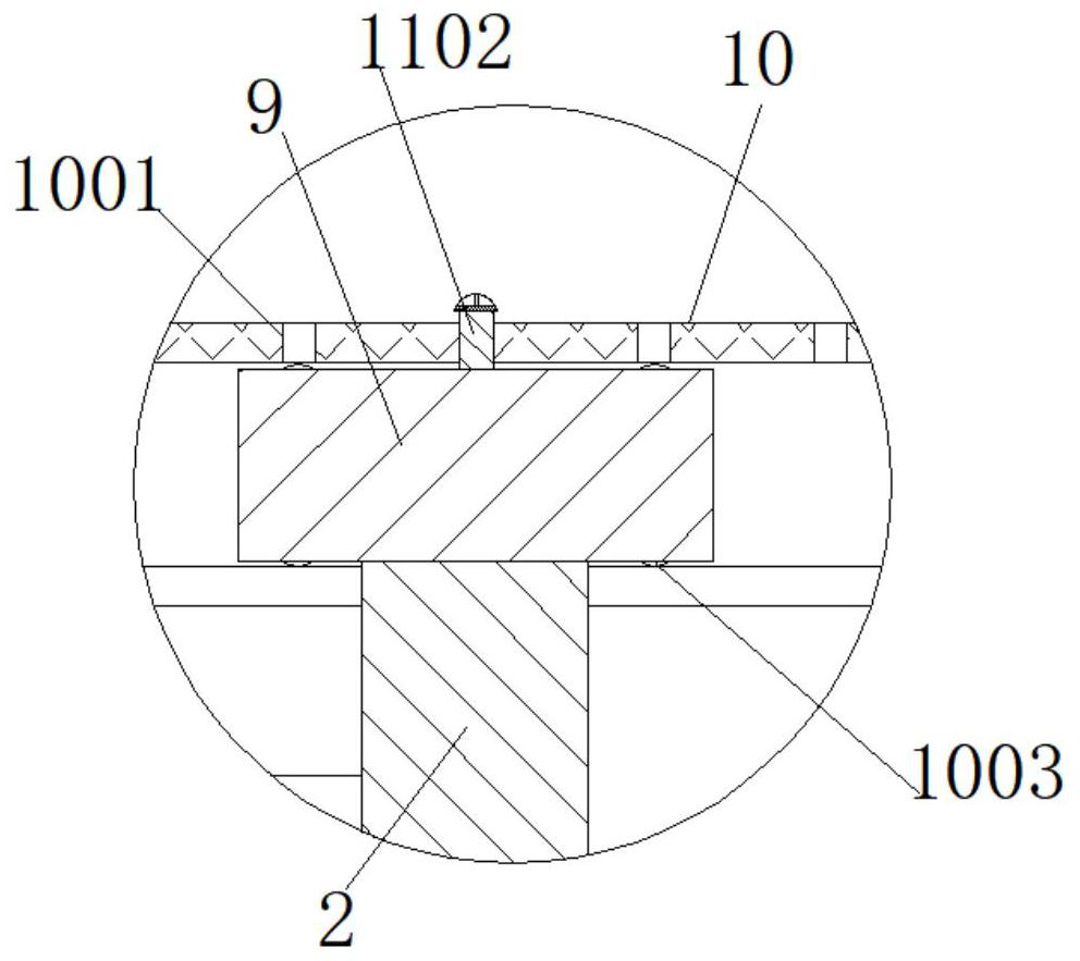
[0029] refer to Figure 1-3 , a water-saving water supply and drainage device, including a sewage tank 1, a cover plate 3 is fixed on the top of the sewage pool 1, and a bearing fixing box 8 is embedded in the middle of the cover plate 3, and the middle of the bearing fixing box 8 is connected with a transmission Pipe 7, and the outer wall of the bottom end circumference of transmission pipe 7 is fixed with three reamers 12 that are distributed in the shape of fan blades, and the middle of the bottom of sewage pool 1 is embedded with a drainage bucket-15 in a hemispherical structure, and the drainage bucket-15 The circumferential inner wall is fixed with two coaxial annular retaining rings 13 from top to bottom, the distance between two adjacent annular retaining rings 13 is equal to the distance between two adjacent reamers 12, and the drain bucket The outer wall of the circumference of 15 is provided with drain holes 14 distributed equidistantly, and the diameter of a single...

Embodiment 2

[0040] refer to Figure 4-5, a water-saving water supply and drainage device. Compared with Embodiment 1, this embodiment also includes a drainage bucket 18 with a long groove structure at the bottom of the sewage pool 1. A transmission shaft 19 runs through the inside of the drainage bucket 18, and the transmission The circumferential outer wall of the shaft 19 is provided with equidistantly distributed arc-shaped cutters 20 , and the bottom inner wall of the drain barrel 2 18 is fixed with equidistantly distributed arc-shaped guide plates 21 .

[0041] Working principle: Different cutting methods have the same cutting effect, which is intended to block the waste cutting at the bottom.


PUM


Abstract

The invention belongs to the technical field of water supply and drainage, and particularly relates to a water-saving type water supply and drainage device. According to the problem that an existing water supply and drainage device can be blocked easily when handing with filiform waste deposited at the bottom of a pool, the following scheme is put forward. The water-saving type water supply and drainage device comprises a wastewater pool. A cover plate is fixed to the top end of the wastewater pool, and a bearing fixing box is embedded into the middle of the cover plate. The middle of the bearing fixing box is connected with a transfer pipe in a rotating mode, and three reamers which are distributed in a fan blade shape are fixed to the outer circumferential wall of the bottom end of the transfer pipe. A first drainage barrel which is of a hemisphere-shaped structure is embedded into the middle of the bottom of the wastewater pool, and two annular check rings which are coaxially distributed are fixed to the inner circumferential wall of the first drainage barrel from top to bottom. By adoption of the water-saving type water supply and drainage device disclosed by the invention, when filament-shaped waste is accumulated at the bottom in the using process, only the transfer pipe needs to be rotated so that the reamers can rotate, the waste blocked nearby a drain hole is slitted,and blocking siltation caused by continuous drainage is avoided.

Description

technical field [0001] The invention relates to the technical field of water supply and drainage, in particular to a water-saving water supply and drainage device. Background technique [0002] The equipment mainly involved in water supply and drainage mainly includes indoor water supply, drainage, and fire protection. However, water supply and drainage devices are also widely used in people's lives. The usual water supply and drainage devices are composed of water supply valves and pools. All used wastewater It is directly discharged into the waste water pipeline, without considering the utilization value of some waste water with good water quality, and the waste water with good water quality cannot be reused, which is not conducive to environmental protection and resource conservation. The problem is particularly prominent in today's shortage of water resources, and Some waste water contains some substances that are not easy to decompose, which can easily cause pipe blocka...

Claims


Application Information

Patent Timeline
IPC IPC(8): E03F5/10E03F5/26
CPCE03F5/10E03F5/26
Inventor 李红林张凯
Owner 南京迈科拓信息科技有限公司
Learn More