Clarification tank with submersible reflux pump composite micro-vortex reaction process

A submersible backflow and micro eddy current technology, applied in the field of water treatment, can solve the problems of ineffective utilization of chemical consumption, small collision probability of suspended particles, increase in chemical consumption, etc., and achieve good effluent quality, fast floc formation, and reduced installed capacity. Effect

Active Publication Date: 2013-06-26
NANJING MEISHAN METALLURGY DEV
View PDF1 Cites 4 Cited by
  • Summary
  • Abstract
  • Description
  • Claims
  • Application Information

AI Technical Summary

Problems solved by technology

But it brings a new problem: there is no sludge circulation formed by mechanical agitation, the collision probability of suspended particles in raw water is small, the consumption of chemicals is not effectively utilized, and it is difficult to

Method used


Image

  • Clarification tank with submersible reflux pump composite micro-vortex reaction process
  • Clarification tank with submersible reflux pump composite micro-vortex reaction process

Examples


Example Embodiment

[0028] Example one:

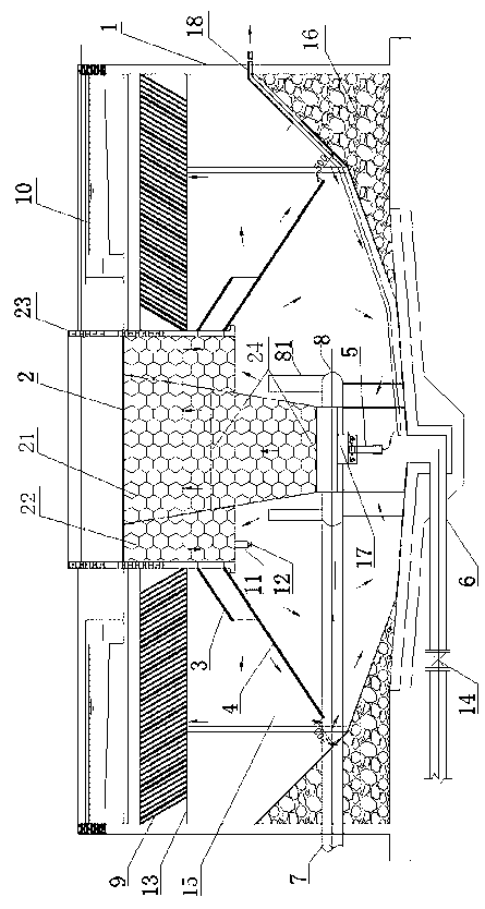
[0029] Such as figure 1 As shown, the clarification tank adopting the submersible reflux pump composite micro-vortex reaction process includes the structure of the tank body 1. The center tube 2 is arranged in the center of the tank body 1. The center tube 2 should be located at the geometric center of the tank body 1 when looking down, and the deviation should not exceed 0.1 m, made of steel plate. The central cylinder 2 is divided into a first reaction zone 21 and a second reaction zone 22. The first reaction zone 21 is in the shape of a conical cylinder. The outer reaction zone 21 is welded with a second reaction zone 22, and the second reaction zone 22 is cylindrical, and the bottom is Made of annular steel, the inner ring of the second reaction zone 22 is welded to the first reaction zone, and the outer ring is sealed with a concrete peripheral tube 23. Both the first reaction zone 21 and the second reaction zone 22 are filled with micro-vortex floccula...

Example Embodiment

[0038] Embodiment two:

[0039] As a preferred solution of the present invention, the other technical features are the same as the first embodiment. The difference is that the bottom of the pool is also laid along the gentle slope with a small mud drain pipe 18 that drains upwards to the outside of the pool. The role of auxiliary mud discharge ensures that the part of the submersible reflux pump is not siltated by sediment and affects its heat dissipation.


PUM


Abstract

The invention discloses a clarification tank. On a basis of a micro-vortex flocculation technology, a device which can form sludge circulation is adopted, such that advantages of traditional water processing processes can be preserved, and defects thereof can be made up. Therefore, an optimal treatment effect can be achieved. According to the clarification tank with the submersible reflux pump composite micro-vortex reaction process, the tank comprises a tank body structure. A central cylinder is arranged at the center of the tank body. A water inlet pipe is arranged at the middle-lower part of the tank body. The bottom of the tank is provided with a gentle slope and a sludge discharge pipe. The central cylinder comprises a reaction first zone and a reaction second zone. The reaction first zone has a tapered cylindrical shape. The reaction second zone is welded on the periphery of the reaction first zone. The bottom of the reaction second zone is annular and is manufactured with steel. The inner ring is welded with the reaction first zone, and a concrete peripheral cylinder is sealed on the outer ring. Micro-vortex flocculators are filled in the reaction first zone and the reaction second zone. A flow guide device is arranged on the bottom of the side of the reaction second zone. An umbrella-shaped plate is arranged below the flow guide device. A submersible reflux pump is arranged on the bottom of the reaction first zone. A multi-point water distribution system is also arranged at an end of the water inlet pipe.

Description

technical field [0001] The invention belongs to the technical field of water treatment, and in particular relates to a clarifier adopting a submersible reflux pump and conforming to a micro-vortex reaction process. Background technique [0002] The coagulation treatment process of water and wastewater includes three stages: mixing of water and chemicals, reaction and separation of flocs and water. The clarifier is a special equipment that completes the above three processes and integrates them. The medium used to trap and separate impurity particles in the clarifier is suspended sludge. In the clarifier, the sediment is lifted and placed in a uniformly distributed suspension, forming a high concentration of stable active sludge layer in the tank. The raw water flows from bottom to top in the clarifier, and the sludge layer can be in a dynamic equilibrium state in the rising water flow due to gravity. When the raw water passes through the activated sludge layer, using ...

Claims


Application Information

Patent Timeline
IPC IPC(8): C02F1/52
Inventor 叶同清刘荣军李伟
Owner NANJING MEISHAN METALLURGY DEV
Why Eureka
Try Eureka