
A gauze conveying device capable of preventing the gauze from being off-line

A technology of conveying device and gauze, which is applied in the directions of transportation and packaging, thin material processing, and winding strips, etc., can solve the problems of easy pulling of gauze, changing the size of gauze holes, and short gauze.

Active Publication Date: 2020-12-15
ANHUI JIAOYANG SOFT DOOR
View PDF14 Cites 0 Cited by
  • Summary
  • Abstract
  • Description
  • Claims
  • Application Information

AI Technical Summary

Problems solved by technology

[0003] However, when the gauze has just been produced, due to the short length of the gauze, the gauze cannot be wound on the guide roller for transmission, and it is necessary to manually wind the gauze on the guide roller after the gauze is produced longer On the roll, during manual winding, because the gauze is produced, the gauze is interlaced by the warp and weft, so the gauze head of the newly produced gauze is not fixed, which will cause the gauze The yarn at the front end falls off; and when the gauze is just produced, because the length is too short, it can only be piled up together, so it is easy to pull the gauze and change the shape of the gauze hole when manually sorting and selecting the gauze. The size affects the quality of the gauze; when the gauze produced is manually wound on the guide roller, the distance between the gauze and the two ends of the guide roller after the gauze is placed on the guide roller cannot be well controlled manually, which will make the When the gauze is wound on the paper tube in the later stage, the left and right are uneven, so it is necessary to frequently fine-tune the position of the gauze on each guide roller

Method used


Image

  • A gauze conveying device capable of preventing the gauze from being off-line
  • A gauze conveying device capable of preventing the gauze from being off-line
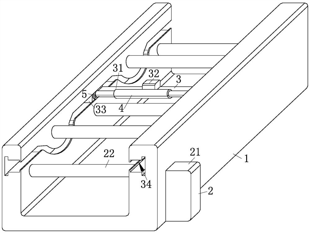
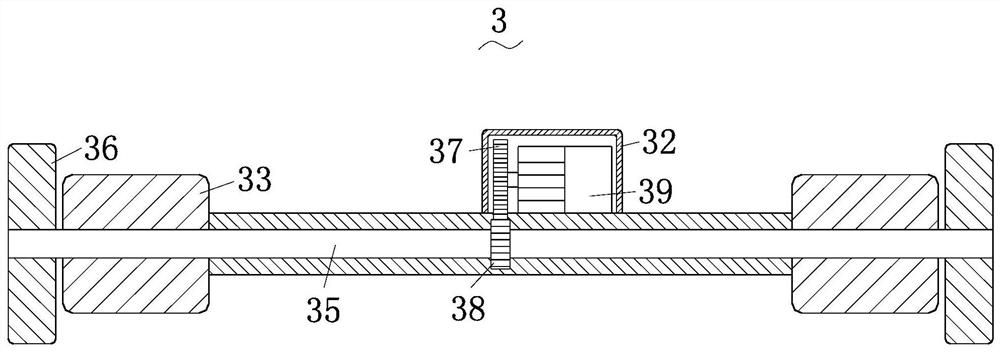
  • A gauze conveying device capable of preventing the gauze from being off-line

Examples


Embodiment Construction

[0022] In order to make the technical means, creative features, goals and effects achieved by the present invention easy to understand, the present invention will be further described below in conjunction with specific embodiments.

[0023] Such as Figure 1-Figure 6 As shown, a gauze conveying device with gauze off-line prevention described in the present invention includes a base 1, a rotating mechanism 2, a moving mechanism 3, a clamping mechanism 4 and an adjusting mechanism 5, and the base for fixing 1 is equipped with the rotating mechanism 2 for guiding the gauze, the base 1 for fixing slides with the moving mechanism 3 for moving, and the moving mechanism 3 for moving is fixed with a The clamping mechanism 4 of the net, the moving mechanism 3 for moving is fixed with the adjusting mechanism 5 for adjusting the clamping mechanism 4, the adjusting mechanism 5 for adjusting the clamping mechanism 4 The moving mechanism 3 for moving is fixed at one end that is away from t...


PUM


Abstract

The invention relates to the field of gauze production, and particularly relates to a gauze conveying device capable of preventing gauze from being disengaged. The gauze conveying device comprises a base, a rotating mechanism, a moving mechanism, a clamping mechanism and an adjusting mechanism. Through the arrangement of the clamping mechanism, a gauze head of a gauze can be clamped conveniently,and thus in the moving process of the gauze, the situation that yarn is disengaged in the pulling process of the gauze head of the gauze is avoided conveniently. One end of the adjusting mechanism isfixed to the clamping mechanism, and the other end of the adjusting mechanism is fixed to the moving mechanism, so that when the adjusting mechanism is rotated, the length of the clamping mechanism isadjusted through the adjusting mechanism, the gauze head of the gauze is clamped completely by the clamping mechanism conveniently, the distances between the two ends of the gauze and the base are controlled conveniently, the distances between the gauze and the two ends of the base are the same in the moving process, and the gauze can be wound around a paper tube forwards advantageously when thegauze is guided through the rotating mechanism subsequently.

Description

technical field [0001] The invention relates to the field of gauze production, in particular to a gauze conveying device capable of preventing the gauze from going off-line. Background technique [0002] Gauze is widely used in home, office, hotel, etc. to prevent mosquitoes and insects, and the width is from 0.6m to 1.5m. The gauze has the advantages of good toughness, corrosion resistance, easy cleaning and not easy to deform. Screens can be divided into blue and white passivated, painted, plastic-coated screens, stainless steel screens, aluminum alloy wire screens, fiberglass screens, invisible screens, plastic screens, etc. [0003] However, when the gauze has just been produced, due to the short length of the gauze, the gauze cannot be wound on the guide roller for transmission, and it is necessary to manually wind the gauze on the guide roller after the gauze is produced longer On the roll, during manual winding, because the gauze is produced, the gauze is interlaced...

Claims


Application Information

Patent Timeline
Patent Type & Authority Patents(China)
IPC IPC(8): B65H20/16B65H23/26B65H18/10B65H20/02
CPCB65H18/10B65H20/02B65H20/16B65H23/26B65H2701/1133
Inventor 蒋志孟
Owner ANHUI JIAOYANG SOFT DOOR
Learn More