Heavy hinge

A hinged, heavy-duty technology, applied in the field of hardware, can solve problems such as inability to apply heavy-duty structures, limit the thickness of connecting rods, blocking or jamming, etc., to achieve the effect of being easy to achieve and maintain, and enhancing the degree of locking

Pending Publication Date: 2020-02-21
吴朋辉
View PDF0 Cites 1 Cited by
  • Summary
  • Abstract
  • Description
  • Claims
  • Application Information

AI Technical Summary

Problems solved by technology

Due to the inclusion of a plurality of interacting connecting rods, there are many hinge points, the force acting on the slider 40 is a comprehensive force in all directions, and the rotation of the connecting rod acts on the slider 40 to achieve linear sliding, involving rotation and In this structure, on the one hand, when the force is transmitted, it is easy to be affected by the force offset caused by the structure and the force transmission is not smooth, resulting in unsmooth sliding, and the hinge point, slider 40 and If the gap fit between the slide rails 30 has a large error, it is easy to cause sliding blockage or jamming; on the other hand, the thickness of each connecting rod is limited, so that the connecting rods are thinner and the load-bearing capacity is smaller, which may easily cause the sliding stay to spread out. After that, it closes automatically, resulting in a short service life of the sliding stay and cannot be used in heavy structures

Method used


Image

  • Heavy hinge
  • Heavy hinge
  • Heavy hinge

Examples


Embodiment Construction

[0026] In order to make the purpose, technical solution and advantages of the present invention clearer, the technical solution of the present invention will be described in detail below. Apparently, the described embodiments are only some of the embodiments of the present invention, but not all of them. Based on the embodiments of the present invention, all other implementations obtained by persons of ordinary skill in the art without making creative efforts fall within the protection scope of the present invention.

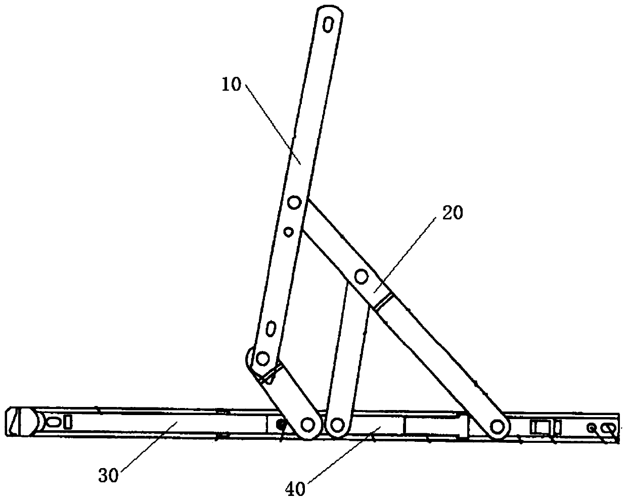
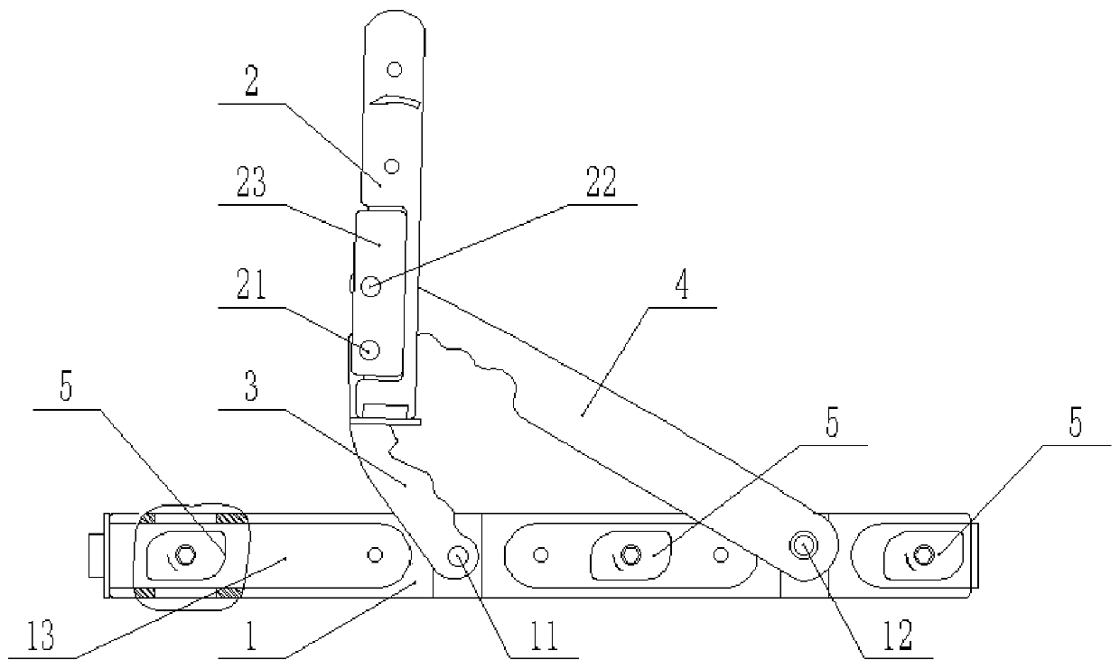
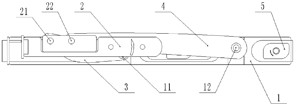
[0027] The purpose of this specific embodiment is to provide a heavy-duty hinge, which realizes the opening and closing of the hinge through the rotating structure. Compared with the sliding stay in the prior art, the smoothness, portability and ease of operation of the switch are enhanced, and Increased load-bearing capacity.

[0028] Hereinafter, the embodiments will be described in detail in conjunction with the accompanying drawings. In addition, the examp...


PUM


Abstract

The invention discloses a heavy hinge, and belongs to the technical field of hardware. The heavy hinge is used for connecting two components needing to be opened and closed. The heavy hinge comprisesa bottom plate, a supporting arm, a short connecting plate and a long connecting plate, the bottom plate is used for being connecting with one of the two components, the supporting arm is connecting with the other component, the short connecting plate and the long connecting plate are used for connecting the supporting arm and the bottom plate, the first end of the short connecting plate is hingedto the supporting arm to form a first supporting arm hinge point, the second end of the short connecting plate is hinged to the bottom plate to form a first bottom plate hinge point, the first end ofthe long connecting plate is hinged to the supporting arm to form a second supporting arm hinge point, the second end of the long connecting plate is hinged to the bottom plate to form a second bottom plate hinge point, a first spacing is arranged between the first supporting arm hinge point and the second supporting arm hinge point, and a second spacing is arranged between the first bottom platehinge point and the second bottom plate hinge point. According to the heavy hinge, opening and closing of the hinge are achieved through a rotating structure; and compared with a sliding support in the prior art, the smoothness, the portability and the workability of a switch are enhanced, and the bearing capacity is improved.

Description

technical field [0001] The invention relates to the technical field of hardware, and more specifically, to a heavy-duty hinge. Background technique [0002] Hinges usually refer to hinges, and hinges used in doors and windows that can be opened are usually called sliding stays, that is, sliding stay hinges. Such as figure 1 As shown, the sliding stay hinges in the prior art are all composed of a bracket arm 10 , a cantilever 20 , a slide rail 30 and a slider 40 . Wherein, the slide block 40 is installed on the slide rail 30, and there are multiple cantilevers 20, which can be divided into long cantilever, short cantilever and oblique cantilever according to length and connection position. The long cantilever is hinged between the slide rail 30 and the support arm 10 , the short cantilever is hinged between the slider 40 and the support arm 10 , and the oblique cantilever is hinged between the slider 40 and the long cantilever. Both the bracket arm 10 and the cantilever ar...

Claims


Application Information

Patent Timeline
Patent Type & Authority Applications(China)
IPC IPC(8): E05C17/34
CPCE05C17/34
Inventor 吴朋辉
Owner 吴朋辉
Why Eureka
Try Eureka