
Material overheating aging and gas pyrolysis detection test device

A technology of pyrolysis and test equipment, which is applied in measuring equipment, analysis materials, weather resistance/light resistance/corrosion resistance, etc., and can solve problems such as neglecting physical and chemical properties

Pending Publication Date: 2020-02-21
STATE GRID GASU ELECTRIC POWER RES INST
View PDF0 Cites 0 Cited by
  • Summary
  • Abstract
  • Description
  • Claims
  • Application Information

AI Technical Summary

Problems solved by technology

However, only attention is paid to the decomposition characteristics of a single gas or a mixed gas under local overheating faults, while the joint aging of gas and solid materials and the mechanical properties after gas decomposition and solid aging are ignored.

Method used


Image

  • Material overheating aging and gas pyrolysis detection test device

Examples


Embodiment 1

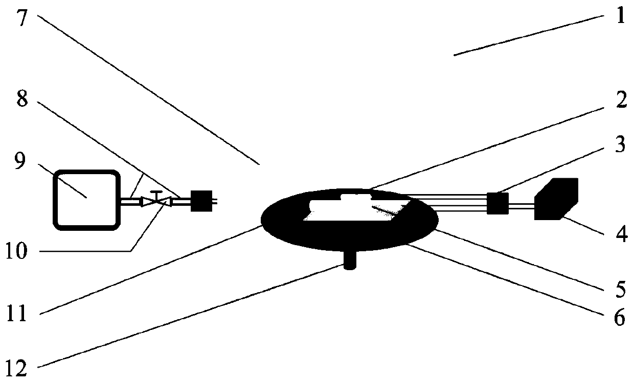
[0019] Such as figure 1 The specific structure of a field-applied maintenance isolation plate shown is as follows:

[0020] The whole device is divided into a solid material overheating aging part, a gas overheating pyrolysis detection part and a sample placement part.

[0021] The sample placement part puts solid insulating material and gas inside the stainless steel test chamber 1 , and the insulating material sample is placed on a red copper tray 11 fixed by stainless steel pillars 12 .

[0022] The solid material overheating and aging part is composed of a temperature sensor 2, an aviation plug 3, a temperature controller 4 and a heating tube 5. An aviation plug 3 is installed on the side wall of the test cavity 1, and the aviation plug 3 is placed inside the test cavity 1, and a temperature sensor 2 and a heating pipe 5 are installed on the inside, and a temperature controller 4 is installed on the outside. The temperature controller 4 adopts PID to adjust and control t...


PUM


Abstract

The invention is suitable for the technical field of high voltage and insulation, and particularly relates to a material overheating aging and gas pyrolysis detection test device. The device comprisesa test cavity, wherein a tray is arranged in the test cavity through a stainless steel support, the tray is used for placing an insulation material test product, aviation plugs are arranged on the two symmetrical side walls of the test cavity, one aviation plug is arranged on the inner side of the test cavity, a temperature sensor and a heating pipe are arranged at the inner side of the test cavity, and a temperature controller is arranged at an outer side; and a decomposed gas component detection system is arranged on the other aviation plug through a gas path pipeline. The device disclosedby the invention provides guidance and evaluation methods for mastering the mutual influence mechanism between the decomposition of the gas solid materials and the performance change of the solid after local overheating fault by the engineers and scientific researchers.

Description

technical field [0001] The invention is applicable to the technical field of high voltage and insulation, and specifically relates to a detection and test device for overheating aging of materials and pyrolysis of gases. Background technique [0002] Partial discharges will be caused by burrs and other sharp points in bulk insulation equipment, and the concentration of local field strength will cause local temperature rise of the insulation. Or the occurrence of dielectric loss, excessive conductivity, magnetic circuit failure and other reasons cause local temperature rise abnormality, etc., which will lead to local overheating faults. The gas in the chamber undergoes a decomposition reaction under the action of high temperature. At the same time, since the actual gas-insulated equipment contains insulator solid materials that act as seals or supports, once the equipment has a local overheating fault, it will directly cause the solid insulating material to age and decompose...

Claims


Application Information

Patent Timeline
IPC IPC(8): G01N17/00
CPCG01N17/00
Inventor 张广东杨军亭孙涛陈宏刚杨勇朱生鸿彭鹏王津马振祺张玉王继娟包艳艳张家午
Owner STATE GRID GASU ELECTRIC POWER RES INST
Learn More