

Ventilation device suitable for complex environment and used for removing dust
A complex environment and ventilation device technology, applied in the field of ventilation, can solve problems affecting production efficiency, the angle of the air inlet cannot be adjusted, and the ventilation device is inconvenient to move, etc., to achieve the effects of reducing impact, large adjustable range, and saving water resources
- Summary
- Abstract
- Description
- Claims
- Application Information
AI Technical Summary
Problems solved by technology
Method used
Image

Examples
Embodiment 1
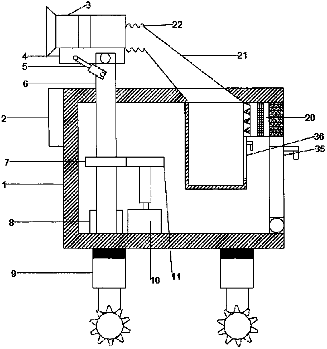
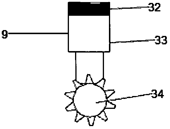
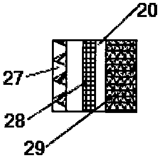
[0028] see Figure 1~5, in the embodiment of the present invention, a kind of ventilating device that is suitable for complicated environment, eliminates dust, comprises shell 1, air inlet device 3, mobile device 9 and air outlet device 20, and the inside left side of described shell 1 is provided with fixed connection Bearing 8, said bearing 8 is rotationally connected with the lower end of rotating rod 6, said rotating rod 6 is provided with a fixedly connected first gear 7 at 1 / 3 from bottom to top, and the right side of said first gear 7 is arranged There are second gears 11 meshing with each other, the second gear 11 is fixedly connected to the upper end of the sleeve, the sleeve is fixedly connected to the upper end of the output shaft of the motor 10, and the lower end of the motor 10 is arranged in the bottom of the housing 1 On the surface, the motor 10 is a servo motor capable of forward and reverse rotation. The rotating rod 6 runs through the top of the housing 1 a...
Embodiment 2
[0030] see Figure 2-7 , in the embodiment of the present invention, a kind of ventilating device that is suitable for complicated environment, eliminates dust, comprises shell 1, air inlet device 3, mobile device 9 and air outlet device 20, and the inside left side of described shell 1 is provided with fixed connection Bearing 8, said bearing 8 is rotationally connected with the lower end of rotating rod 6, said rotating rod 6 is provided with a fixedly connected first gear 7 at 1 / 3 from bottom to top, and the right side of said first gear 7 is arranged There are second gears 11 meshing with each other, the second gear 11 is fixedly connected to the upper end of the sleeve, the sleeve is fixedly connected to the upper end of the output shaft of the motor 10, and the lower end of the motor 10 is arranged in the bottom of the housing 1 On the surface, the motor 10 is a servo motor capable of forward and reverse rotation. The rotating rod 6 runs through the top of the housing 1 ...
PUM
 Abstract
Description
Claims
Application Information