Data transmission method, terminal and network equipment

A data transmission method, technology of network equipment, applied in the field of terminal and network equipment, data transmission method, can solve the problem of not being able to support simultaneous transmission of PUSCH

Active Publication Date: 2020-02-25
DATANG MOBILE COMM EQUIP CO LTD
View PDF6 Cites 7 Cited by
  • Summary
  • Abstract
  • Description
  • Claims
  • Application Information

AI Technical Summary

Problems solved by technology

[0004] The purpose of the present invention is to provide a data transmission method, terminal and network equipment to s

Method used


Image

  • Data transmission method, terminal and network equipment
  • Data transmission method, terminal and network equipment
  • Data transmission method, terminal and network equipment

Examples


Embodiment Construction

[0094] In order to make the technical problems, technical solutions and advantages to be solved by the present invention clearer, the following will describe in detail with reference to specific embodiments and accompanying drawings.

[0095] In order to enable those skilled in the art to better understand the technical solutions of the embodiments of the present invention, the following descriptions are given first.

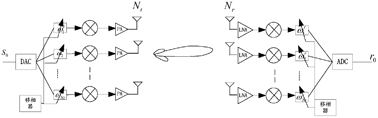
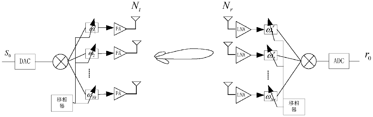
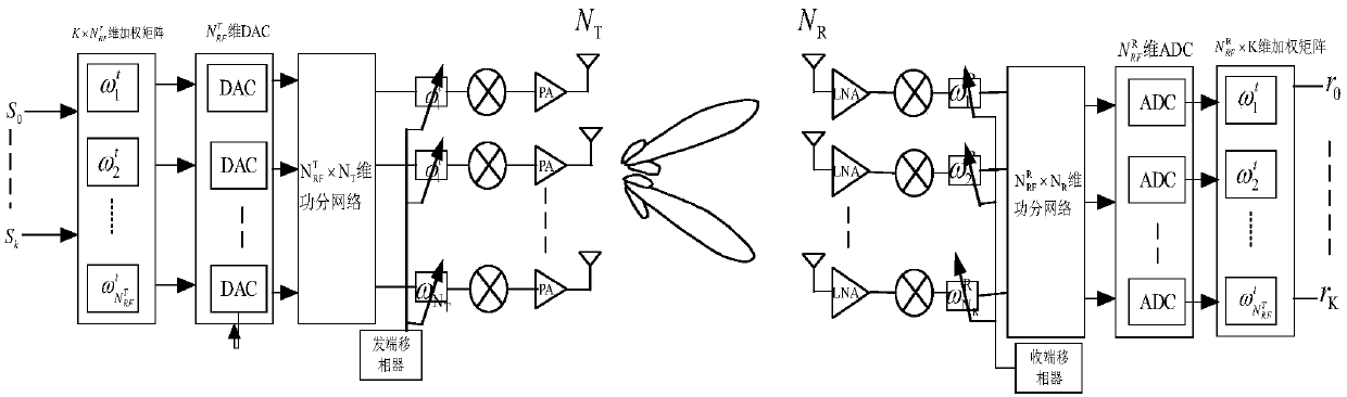
[0096] In view of the important role of MIMO (Multiple-Input Multiple-Output) technology in improving peak rate and system spectrum utilization, LTE (Long Term Evolution, long-term evolution) or LTE-A (LTE-Advanced, enhanced long-term Evolution) and other wireless access technology standards are built on the basis of MIMO+OFDM (Orthogonal Frequency Division Multiplexing, Orthogonal Frequency Division Multiplexing) technology. The performance gain of MIMO technology comes from the spatial freedom obtained by multi-antenna systems. Therefore, one of the most impor...


PUM


Abstract

The invention provides a data transmission method, a terminal and network equipment, and solves the problem that the existing specification cannot support simultaneous transmission of a PUSCH from a multi-antenna panel. The transmission method provided by the invention comprises the following steps: receiving physical uplink shared channel (PUSCH) scheduling information sent by a network device, with the PUSCH scheduling information comprising first indication information and second indication information, the first indication information being used for indicating a data layer included in a PUSCH, and the second indication information being used for indicating a precoding matrix; and according to the precoding matrix indicated by the second indication information, mapping a data layer included in the PUSCH to at least two target antenna panels for sending, with the target antenna panel being an antenna panel for transmitting the PUSCH in the at least two antenna panels of the terminal.According to the embodiment of the invention, the aim of simultaneously transmitting the data layer of the PUSCH from a plurality of antenna panels is fulfilled.

Description

technical field [0001] The present invention relates to the technical field of communication applications, in particular to a data transmission method, terminal and network equipment. Background technique [0002] Currently, a UE (User Equipment, user equipment or terminal) equipped with multiple transmit antennas can perform uplink beamforming. In order to determine the uplink UL beamforming matrix, a UE in a radio resource control connected (RRC_CONNECTED) state may be semi-statically configured with multiple UE-specific uplink SRS (Sounding Reference Signal, Sounding Reference Signal) resources. The SRS signal transmitted on each SRS resource is beam-formed with a specific beam-forming matrix. The UE transmits these SRS resources in uplink. TRP measures the signal quality of different SRS resources and selects the preferred SRS resource. The TRP sends the index of the selected SRS resource (SRS resource indicator, SRI) to the UE via DCI (Downlink Control Information, d...

Claims


Application Information

Patent Timeline
IPC IPC(8): H04B7/0456H04B7/06H04W72/04H04W72/08H04L5/00H04W72/12
CPCH04B7/0456H04B7/0626H04B7/0695H04W72/046H04L5/0048H04W72/542H04W72/23H04W72/1268H04B7/0691H04B7/0404H04L5/0053H04L5/0044H04L5/0057H04L5/0023H04B7/06966H04B7/0408H04B7/0617H04B7/0682H04B7/0417
Inventor 苏昕陈润华高秋彬黄秋萍缪德山
Owner DATANG MOBILE COMM EQUIP CO LTD
Why Eureka
Try Eureka