
Synthetic Aperture Antenna Device for Transmitting Signals of a Satellite Navigation System Comprising a Carrier and Means for Determining its Trajectory

Inactive Publication Date: 2012-07-26
THALES SA
View PDF5 Cites 2 Cited by
  • Summary
  • Abstract
  • Description
  • Claims
  • Application Information

AI Technical Summary

Benefits of technology

[0008]The invention limits the complexity of such transmit antennas by reducing their dimension and the complexity of their processing.
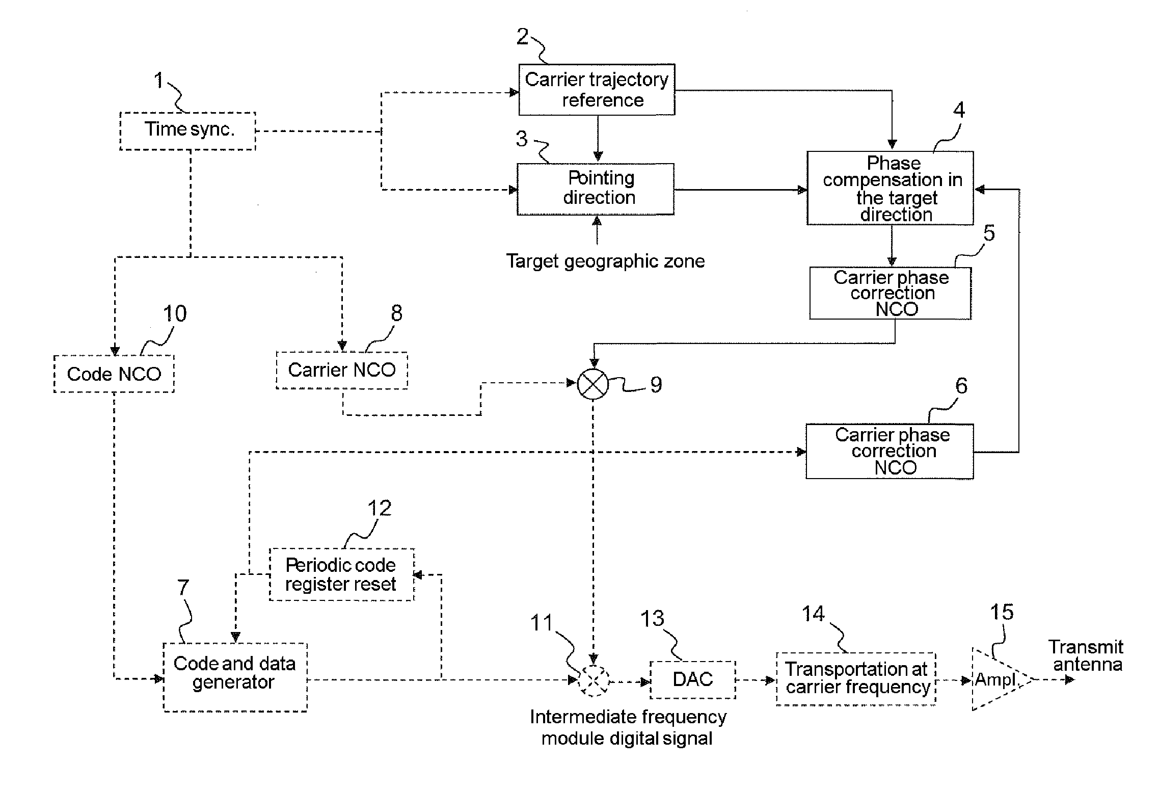
[0010]Such a device makes it possible to limit the complexity of the transmit antenna by reducing the processing load. Moreover, synthetic antenna processing makes it possible to obtain considerable gains in directivity in any target direction, without common measurement with those that can be reached by network antennas because of the bulk and the number of individual antennas that would then be necessary, thus making it possible to improve the transmit gain in the direction of the chosen zone, while masking the transmission in the other directions, and making location outside the defined zone impossible. Because of the simplicity of the proposed synthetic antenna processing, it is possible to carry out simultaneous transmission for different target directions associated with each satellite.
[0018]Such an embodiment makes it possible to retain the conventional architecture of a satellite navigation system transmitter. The phase compensation is carried out at low rate before correlation by the local code.
[0027]The phase correction thus carried out makes it possible to compensate for the change in phase of the signal corresponding to the movement of the carrier in the target direction, then making it equivalent to that which would be delivered in the case of a movement contained in a plane orthogonal to the target direction, thus ensuring that the signals that are transmitted in the target direction are made coherent.

Problems solved by technology

However, these solutions impose restrictive antenna sizes on the satellite, and substantially increase the hardware complexity for the radiofrequency RF stages of the transmitter (as many RF channels as antenna elements) and the computing load.

Method used


Image

  • Synthetic Aperture Antenna Device for Transmitting Signals of a Satellite Navigation System Comprising a Carrier and Means for Determining its Trajectory
  • Synthetic Aperture Antenna Device for Transmitting Signals of a Satellite Navigation System Comprising a Carrier and Means for Determining its Trajectory

Examples


Embodiment Construction

[0029]In general, mention is made of “synthetic antenna” when a deficient resource, such as a lack of space, or an operating restriction, is replaced by time. This assumes a certain spatial stability of the scene: it may be a perfect coherence (SAR, SAS, seismic or echography), or simply a second-order spatial stationarity (aperture synthesis in radioastronomy).

[0030]The techniques of synthetic antennas are known in receive mode in the fields of cartography, of sounding or of echography.

[0031]Specifically, the synthetic antenna, originally applied in receive mode to radar cartography or SAR for “Synthetic Aperture Radar”, uses the specific movement of the vehicle carrying the physical antenna. It artificially manufactures or simulates a large-size antenna, the geometry of which corresponds to the space covered by the antenna when it moves.

[0032]The application to the field of satellite navigation provides new horizons because of the need to respond simultaneously to constraints of l...


PUM


Abstract

A synthetic aperture antenna device for transmitting signals of a system includes a carrier and means for determining its trajectory, and, for each signal respectively associated with a spatial direction, processing means suitable for generating a stationary phase signal over a time window corresponding to the distance traveled by the device throughout the period of coherent integration, before modulation of the received signal, the processing means comprising correction means suitable for correcting the carrier phase of the signal.

Description

CROSS-REFERENCE TO RELATED APPLICATION[0001]This application claims priority to foreign French patent application No. FR 1003025, filed on Jul. 19, 2010, the disclosure of which is incorporated by reference in its entirety.FIELD OF THE INVENTION[0002]The invention relates to a signal transmitter of a satellite navigation system designed to improve the robustness of transmission of the signals in the direction of dedicated reception zones.BACKGROUND[0003]Cooperative transceiver devices of the location or telecommunication type involve a coupling of the receiver to the carrier phase of the received signal.[0004]An example thereof is given by the satellite radio navigation systems GNSS which use a constellation of satellites revolving around the earth in very precisely determined orbits. Thus, it is possible to ascertain at any moment the position of any satellite. The orbits of the satellites are chosen so that, at any time, 6 to 12 satellites are visible at any point on earth. Each s...

Claims


Application Information

Patent Timeline
IPC IPC(8): G01S19/29
CPCG01S19/02
Inventor REVOL, MARC
Owner THALES SA
Learn More