Filter warehousing storage placing rack

A filter and shelf technology, applied to instruments, time registers, single input port/output port registers, etc., can solve the problems of increased difficulty, dust accumulation of filters, inconvenient storage and output, etc. , to achieve the effect of convenient storage and delivery, preventing dust accumulation and increasing service life

Inactive Publication Date: 2020-02-28
安徽川越通信科技有限责任公司
View PDF5 Cites 0 Cited by
  • Summary
  • Abstract
  • Description
  • Claims
  • Application Information

AI Technical Summary

Problems solved by technology

[0003] The filter storage rack is a device for storing filters. However, one of the existing racks is to directly place the filter on the shelf in the open air, so there is a serious problem of dust accumulation on the filter. Phenomenon, there is also a cabinet-type display rack, and although the cabinet-type display rack avoids dust accumulation when placing filters, it is not convenient when entering and exiting the warehouse, and it is not suitable for various models. When the filters are stored at the same time, it is impossible to accurately know the filter model corresponding to each cabinet, which increases the difficulty of storage and storage

Method used


Image

  • Filter warehousing storage placing rack
  • Filter warehousing storage placing rack
  • Filter warehousing storage placing rack

Examples


Embodiment 1

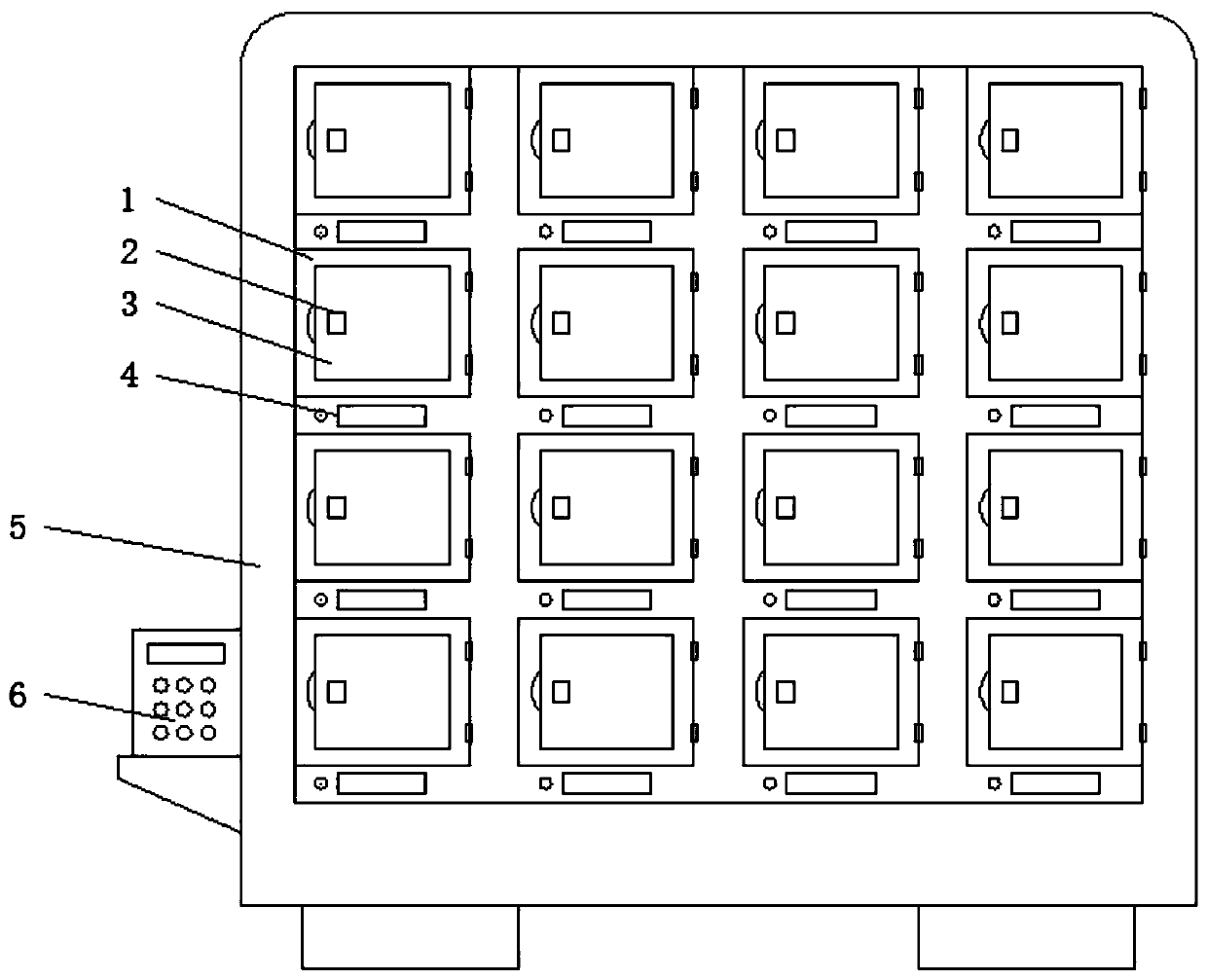
[0027] Embodiment 1, with reference to Figure 1-3 , a kind of storage rack for storing filters, including a main cabinet 5, a controller 6 is arranged on one side of the main cabinet 5, a plurality of sub-cabinets 1 are arranged on the main cabinet 5, and the front surface of the main cabinet 5 is located in the sub-cabinets 1 A display screen 4 is embedded at the bottom, a cabinet door 3 is provided on the cabinet 1, and an electromagnetic control door lock 2 is provided inside the cabinet door 3;

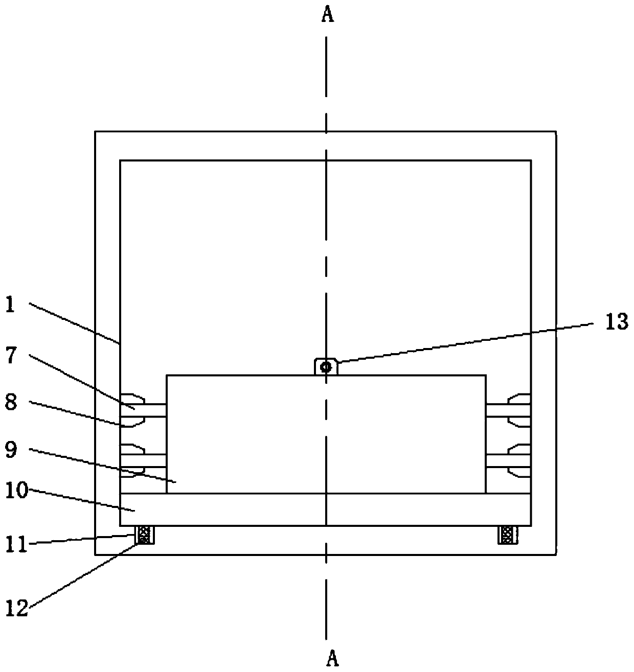
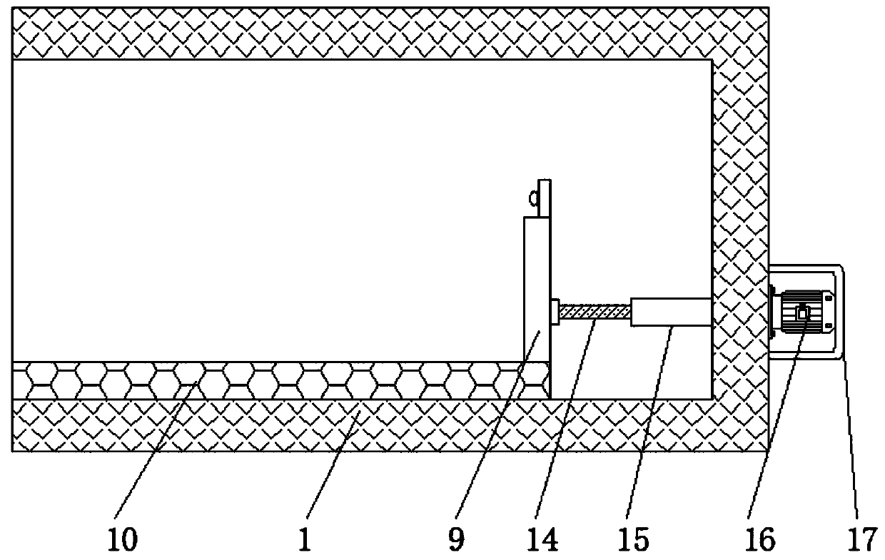
[0028] The interior of the sub-cabinet 1 is provided with a placement board 10, the width of the placement board 10 is the same as that of the sub-cabinet 1, the top of the placement board 10 is provided with a vertical board 9, and the vertical board 9 is provided with a collection camera 13, and one side of the vertical board 9 The center is provided with a threaded rod 14, the inner wall of the sub-cabinet 1 is rotated by a bearing to install a threaded sleeve 15, one end of t...

Embodiment 2

[0037] Embodiment 2, with reference to Figure 1-3 , the present invention also discloses a control system for storing and placing filters in storage, the specific control process is as follows:

[0038] S1, the controller 6 controls the electromagnetic control door lock 2 to open, so that the cabinet door 3 is opened;

[0039] S2. The controller 6 controls the operation of the motor 16 to drive the threaded sleeve 15 to rotate clockwise, so that the threaded rod 14 pushes the vertical plate 9 and the placement plate 10 to slide outside the cabinet 1;

[0040] S3. After the filter is placed on the placement board 10, the controller 6 controls the motor 16 to run again, drives the threaded sleeve 15 to rotate counterclockwise, and retracts the placement board 10 into the sub-cabinet 1;

[0041] S4. The acquisition camera 13 is turned on, scans the filter located on the installation board 10 , acquires the filter model, and displays it on the display screen 4 .

[0042] Combin...


PUM


Abstract

The invention discloses a filter warehousing storage placing rack. The filter warehousing storage placing rack comprises a main cabinet; a controller is arranged at one side of the main cabinet; multiple sub cabinets are arranged on the main cabinet; a placing plate is arranged inside each sub cabinet; a vertical plate is arranged above each placing plate; an acquisition camera is arranged on eachvertical plate; a threaded rod is arranged at the center of one side of eachvertical plate; a threaded sleeve is rotatably installed on the inner wall of eachsub cabinet through a bearing; one end ofeachthreaded sleeve sleeves the corresponding threaded rod; a motor box is arranged on the outer wall of the main cabinet; a motor is arranged inside the motor box; and a rotating shaft of the motor passes through the main cabinet and extends to the insides of the sub cabinets to be rotationally connected with the threaded sleeves. According to the filter warehousing storage placing rack providedby the invention, the correspondingplacing plate which is controlled to move by the motor is arranged in eachsub cabinet, so that when a filter is put into or out of a warehouse, the controller only needs to control the movement of the placing plates, so that the filter can be put into or out of the warehouse very conveniently.

Description

technical field [0001] The invention relates to the field of filter storage equipment, in particular to a storage rack for filter storage. Background technique [0002] The power filter is a filter circuit composed of capacitors, inductors and resistors. The filter can effectively filter out the frequency points of a specific frequency in the power line or frequencies other than this frequency point, obtain a power signal of a specific frequency, or eliminate a Power signal after a specific frequency; [0003] The filter storage rack is a device for storing filters. However, one of the existing racks is to directly place the filter on the shelf in the open air, so there is a serious problem of dust accumulation on the filter. Phenomenon, there is also a cabinet-type display rack, and although the cabinet-type display rack avoids dust accumulation when placing filters, it is not convenient when entering and exiting the warehouse, and it is not suitable for various models. W...

Claims


Application Information

Patent Timeline
Patent Type & Authority Applications(China)
IPC IPC(8): A47B81/00A47B96/02E05B65/52G07C9/00
CPCA47B81/00A47B96/021A47B96/024A47B96/025E05B65/52G07C9/00571G07C9/00896
Inventor 杨国顺
Owner 安徽川越通信科技有限责任公司
Why Eureka
Try Eureka