Installation positioning adjustment device for sun shade in driver's cab of motor train unit and positioning method of installation positioning adjustment device

An adjustment device, installation and positioning technology, applied in anti-glare equipment, vehicle parts, transportation and packaging, etc., can solve the problems of sunshade electric sticking, difficulty in precise positioning, and insufficient adjustment, so as to improve the safety factor of operations and solve the problem of It is not easy to control and avoid the effect of material loss

Pending Publication Date: 2020-02-28
CRRC CHANGCHUN RAILWAY VEHICLES CO LTD
View PDF0 Cites 0 Cited by
  • Summary
  • Abstract
  • Description
  • Claims
  • Application Information

AI Technical Summary

Problems solved by technology

[0002] Because the driver’s cab sunshade is located in the special space of the front of the car, the overall structure is complex. When adjusting, various links will affect each other due to relative position changes, making it difficult to accurately locate. When the curtain is motorized, it is stuck, requiring construction personnel to go to the commissioning site to disassemble the internal components and then re-adjust the construction of the sunshade, which causes a great waste of manpower and material resources

Method used


Image

  • Installation positioning adjustment device for sun shade in driver's cab of motor train unit and positioning method of installation positioning adjustment device
  • Installation positioning adjustment device for sun shade in driver's cab of motor train unit and positioning method of installation positioning adjustment device
  • Installation positioning adjustment device for sun shade in driver's cab of motor train unit and positioning method of installation positioning adjustment device

Examples


Embodiment Construction

[0064] In order to enable those skilled in the art to better understand the technical solutions of the present invention, the present invention will be further described in detail below in conjunction with the accompanying drawings.

[0065] see Figure 1 to Figure 10 shown;

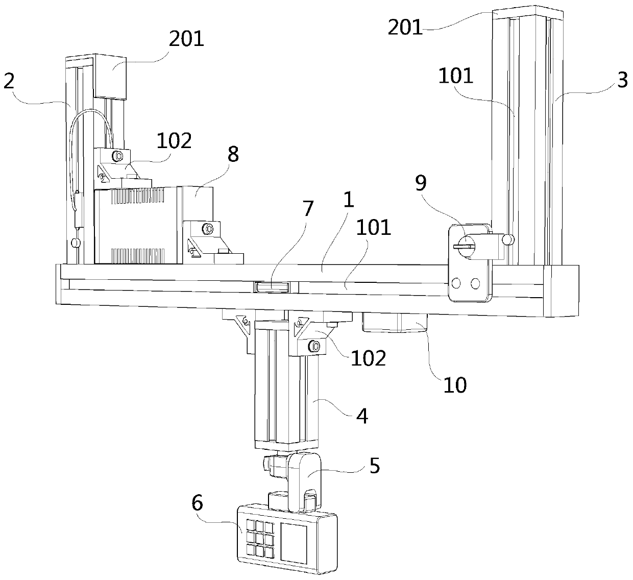
[0066] The EMU driver's cab sunshade of this embodiment is equipped with a positioning adjustment device, which mainly includes:

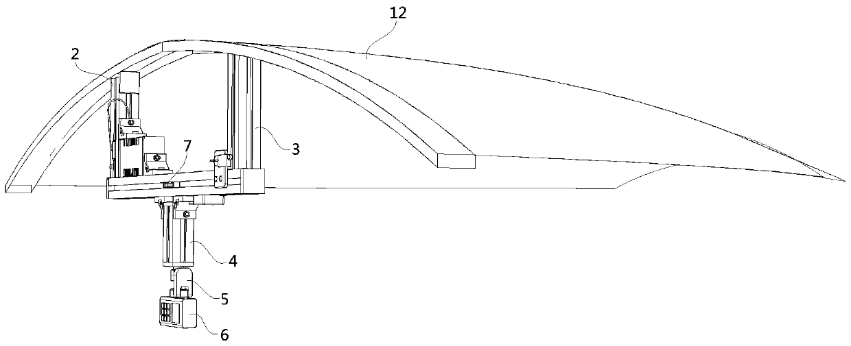
[0067] Structural frame, the device is assembled on the rear side of the sunshade mechanism 12 of the driver's cab of the EMU through the structural frame;

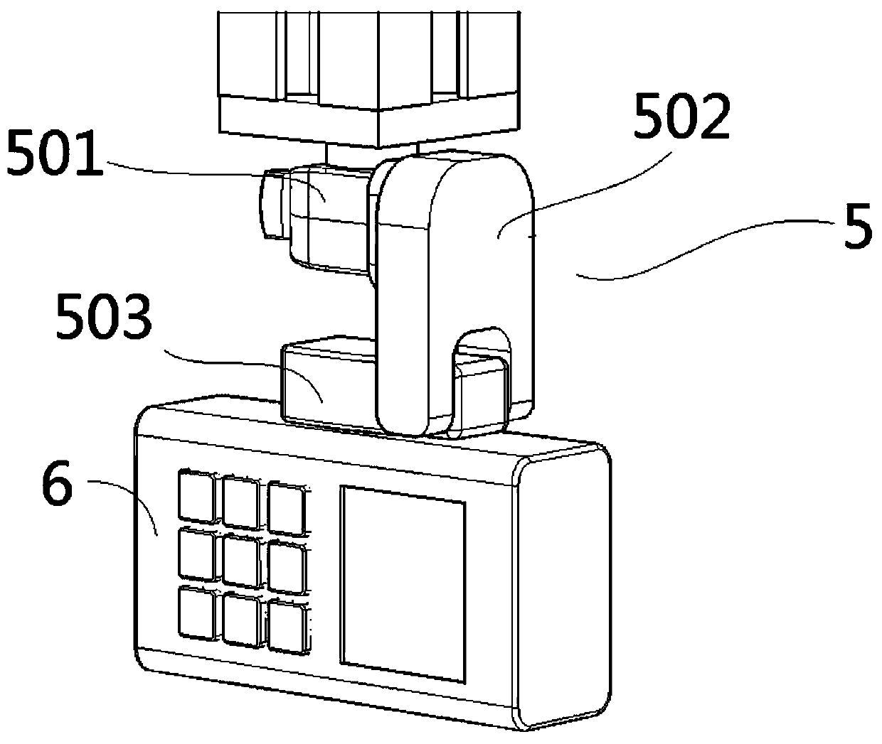
[0068] The lower rotating arm 4 connected to the lower part of the structural frame;

[0069] The lower end of the lower arm 4 is equipped with an infrared rangefinder 6 capable of adjusting the measuring direction;

[0070] An infrared cross positioning probe 11 is installed in the middle of the lower rotating arm 4, and the infrared cross optical fiber emitted by the infrared cross positioning probe 11 faces the fro...


PUM


Abstract

The invention discloses an installation positioning adjustment device for a sun shade in a driver's cab of a motor train unit and a positioning method of the installation positioning adjustment device. The installation positioning adjustment device includes a structural frame, a lower rocker arm connected to the lower part of the structural frame, an infrared distance meter capable of adjusting ameasurement direction, an infrared cross positioning probe and a three-way holder. The infrared distance meter is installed at the lower end of the lower rocker arm, and the infrared cross positioningprobe is installed at the middle position of the lower rocker arm. An infrared cross optical fiber emitted by the infrared cross positioning probe faces the front side of a sun shade mechanism of thedriver's cab. The three-way holder is assembled at the lower end of the lower rocker arm, and the infrared distance meter is movably connected with the lower rocker arm through the three-way holder.The infrared distance meter adjusts the measurement direction through the three-way holder. The installation positioning adjustment device realizes the positioning adjustment of the mechanism in a multi-dimensional space, and effectively improves the quality stability, corresponding tests prove that the percent of pass reaches 100%, and operators do not need to reciprocate to other workshops for repair operation, so that the labor intensity is reduced, and the operation safety coefficient is increased.

Description

technical field [0001] The invention relates to the technical field of installing sunshade curtains for EMUs, in particular to an installation and positioning adjustment device and a positioning method for sunshade curtains in a driver's cab of an EMU. Background technique [0002] Because the driver’s cab sunshade is located in the special space of the front of the car, the overall structure is complex. When adjusting, various links will affect each other due to relative position changes, making it difficult to accurately locate. When the curtain is motorized, it is stuck, requiring construction personnel to go to the commissioning site to disassemble the internal components and then re-adjust the construction of the sunshade, which causes a great waste of manpower and material resources. Contents of the invention [0003] The invention provides a sunshade installation and positioning adjustment device and a positioning method for a driver's cab of an EMU, which can quick...

Claims


Application Information

Patent Timeline
Patent Type & Authority Applications(China)
IPC IPC(8): B60J3/02
CPCB60J3/02
Inventor 胡俊祥牛国营朱晓燕
Owner CRRC CHANGCHUN RAILWAY VEHICLES CO LTD
Why Eureka
Try Eureka