Windproof sand-reducing wall for environment protection

A sand wall and environmental protection technology, applied in the direction of protective equipment, buildings, etc., can solve the problems of normal driving damage, poor effect, and wind and sand entry, and achieve the effects of slowing down the intrusion of wind and sand, improving the living environment, and reducing the content of wind and sand

Inactive Publication Date: 2020-02-28
界首市利能环保技术开发有限公司
View PDF0 Cites 6 Cited by
  • Summary
  • Abstract
  • Description
  • Claims
  • Application Information

AI Technical Summary

Problems solved by technology

Cause a certain degree of damage to the normal running of the train, and have a bad impact on the living environment in the residential area
[0003] The main function of the current windbreak walls along the railway line is to block the wind and sand, and the effect is not good; when the wind and sand blow to one side of the wall, the wind speed on the upper side of the wall is relatively high, making the other side of the wall The reduced air pressure on one side will eventually cause wind and sand to enter the other side of the wall, resulting in a lower effect of ordinary windshield walls
At the same time, if the windbreak wall is built around the village, its effect is still relatively poor

Method used


Image

  • Windproof sand-reducing wall for environment protection
  • Windproof sand-reducing wall for environment protection
  • Windproof sand-reducing wall for environment protection

Examples


Embodiment 1

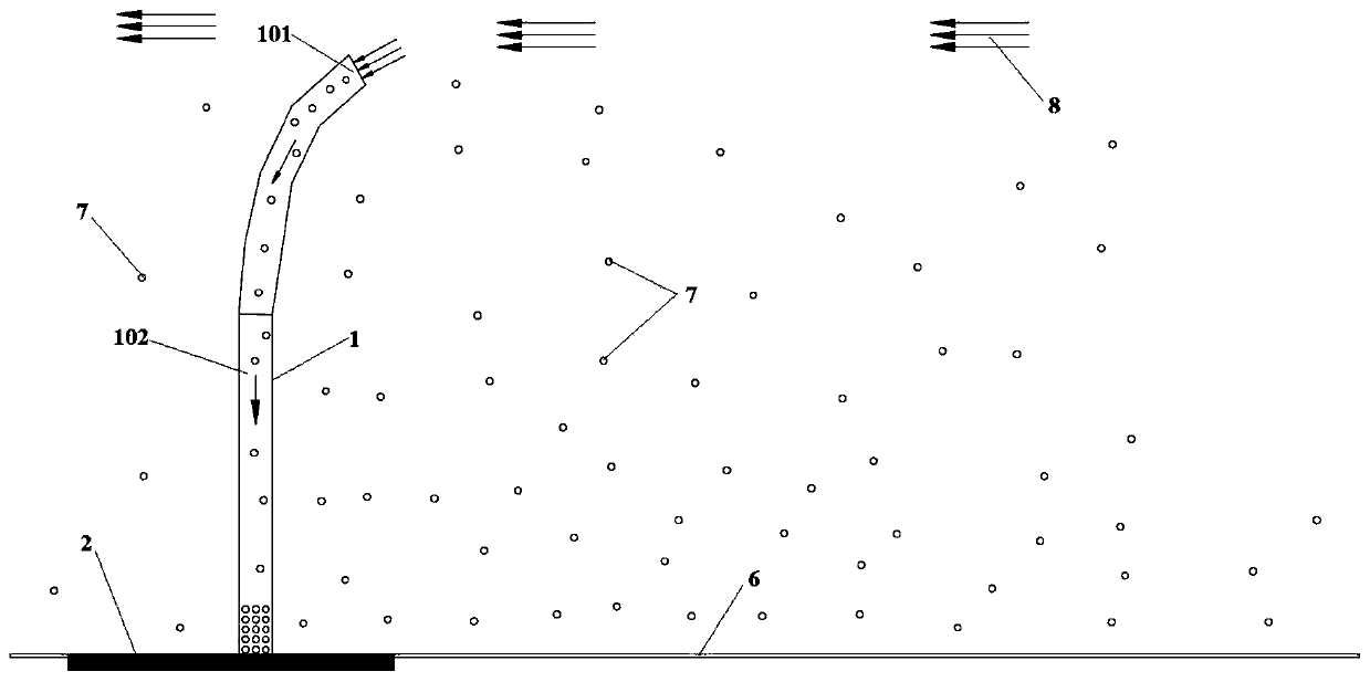
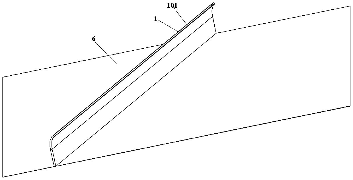
[0037] see Figure 1-6 As shown in the figure, the present invention is a wind-proof and sand-reducing wall for environmental protection, including a wind-blocking and sand-reducing wall 1; the wind-blocking and sand-reducing wall 1 is an inverted "J" type structure; 101; a cavity 102 for sand reduction is provided inside the wind blocking and sand reducing wall 1; a wall base fixing seat 2 for fixing is fixedly installed at the bottom of the wind blocking and sand reducing wall 1; the function of the wall base fixing seat 2 is to block the wind The sand suppression wall 1 is fixed on the ground, and at the same time, a corresponding stable wall base fixing seat is set according to the sandstorm intensity of the environment, so as to ensure its stability.

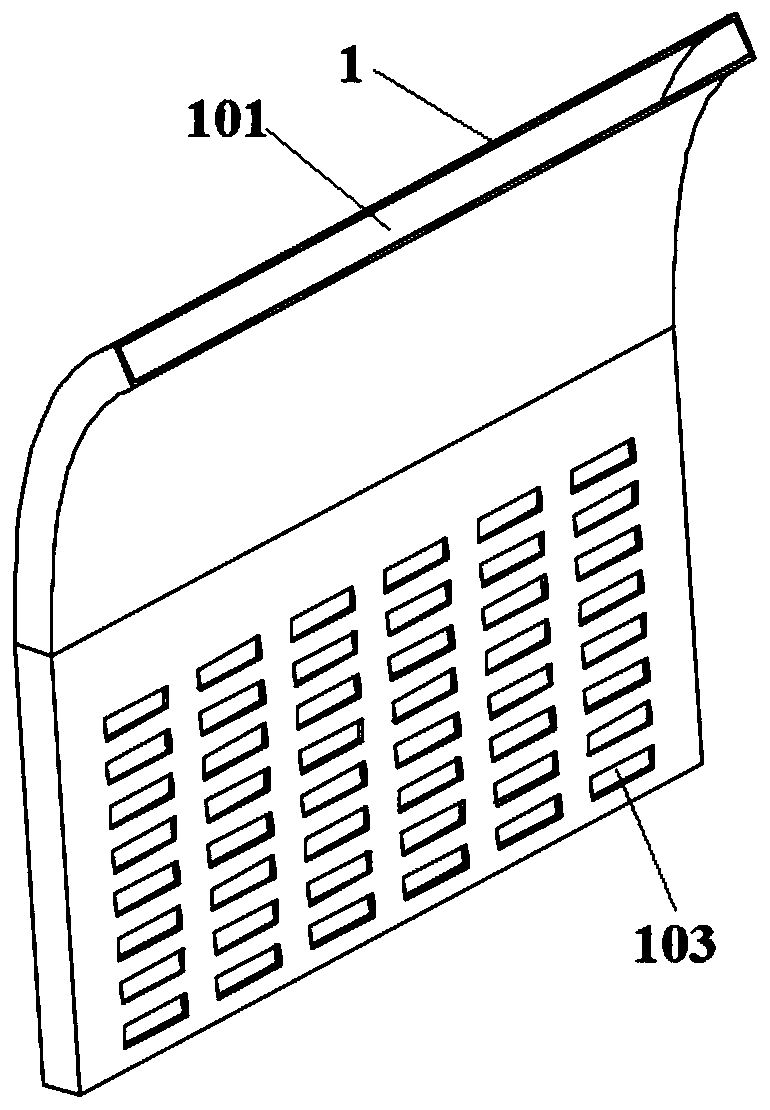
[0038] Preferably, air inlet holes 103 are uniformly arrayed on the inner surface of the wind resistance and sand reduction wall 1; the air inlet holes 101 and the air inlet holes 103 both absorb the sand particles in the w...

Embodiment 2

[0044] see Figure 1-8 As shown in the figure, the present invention is a wind-proof and sand-reducing wall for environmental protection, including a wind-blocking and sand-reducing wall 1; the wind-blocking and sand-reducing wall 1 is an inverted "J" type structure; 101; a cavity 102 for sand reduction is provided inside the wind blocking and sand reducing wall 1; a wall base fixing seat 2 for fixing is fixedly installed at the bottom of the wind blocking and sand reducing wall 1; the function of the wall base fixing seat 2 is to block the wind The sand suppression wall 1 is fixed on the ground, and at the same time, a corresponding stable wall base fixing seat is set according to the sandstorm intensity of the environment, so as to ensure its stability.

[0045]Preferably, air inlet holes 103 are uniformly arrayed on the inner surface of the wind resistance and sand reduction wall 1; the air inlet holes 101 and the air inlet holes 103 both absorb the sand particles in the wi...

Embodiment 3

[0051] see Figure 1-10 As shown in the figure, the present invention is a wind-proof and sand-reducing wall for environmental protection, including a wind-blocking and sand-reducing wall 1; the wind-blocking and sand-reducing wall 1 is an inverted "J" type structure; 101; a cavity 102 for sand reduction is provided inside the wind blocking and sand reducing wall 1; a wall base fixing seat 2 for fixing is fixedly installed at the bottom of the wind blocking and sand reducing wall 1; the function of the wall base fixing seat 2 is to block the wind The sand-reducing wall 1 is fixed on the ground, and at the same time, a corresponding stable wall base fixing seat is set according to the wind-sand intensity of the environment, so as to ensure its stability.

[0052] Preferably, air inlet holes 103 are uniformly arrayed on the inner surface of the wind resistance and sand reduction wall 1; the air inlet holes 101 and the air inlet holes 103 both absorb the sand particles in the win...


PUM


Abstract

The invention discloses a windproof sand-reducing wall for environment protection, and relates to the technical field of wind-sand-resistant walls. The windproof sand-reducing wall for environment protection comprises a wind-resistant sand-reducing wall, wherein a cavity for reducing sand is arranged in the wind-resistant sand-reducing wall; a wall base fixing seat for fixing is fixedly arranged on the bottom part of the wind-resistant sand-reducing wall; air inlet holes are uniformly arrayed on the surface of the inner side of the wind-resistant sand-reducing wall; curved plates for reducingsand are fixed to the surfaces of the inner sides of the air inlet holes; a sand reducing device for collecting sand and discharging air is in through connection to the bottom part of the wind-resistant sand-reducing wall, and is of a circular pipe structure; a rectangular groove is formed in the bottom part of the sand reducing device; arc-shaped sand blocking plates are arranged on the inner surface of the sand reducing device; and an air outlet is formed at the position, located above the part between the two arc-shaped sand blocking plates, on the inner surface of the sand reducing device.According to the windproof sand-reducing wall for environment protection provided by the invention, through the functions of the wind-resistant sand-reducing wall, the sand reducing device and an airpurification device, the wind sand content on the other side of the wind-resistant sand-reducing wall is greatly reduced, the living environment is improved to a certain extent, and the problems suchas the destructive power and the intrusiveness of wind sand are retarded.

Description

technical field [0001] The invention belongs to the technical field of wind and sand walls, and in particular relates to a wind and sand wall for environmental protection. Background technique [0002] At present, railway lines in desert areas, as well as residents on the edge of desert areas, will be disturbed by wind and sand. It will cause damage to the normal running of the train to a certain extent, as well as have a bad impact on the living environment in the residential area. [0003] At present, the main function of the windshield along the railway line is to shield the wind and sand, and its effect is not good. The reduction of air pressure on one side will eventually cause sand to enter the other side of the wall, resulting in a lower effect of ordinary windshield walls. At the same time, if the windshield is built around the village, its effect is still relatively poor. [0004] The present invention is a wind and sand-relief wall for environmental protection; ...

Claims


Application Information

Patent Timeline
Patent Type & Authority Applications(China)
IPC IPC(8): E01F7/02
CPCE01F7/02E01F7/025
Inventor 余小兵
Owner 界首市利能环保技术开发有限公司
Why Eureka
Try Eureka