Hydraulic cutting tool module and combined rock breaking TBM device and method

A technology of hydraulic cutting and cutting tools, which is applied in the direction of earth drilling, mining equipment, tunnels, etc., can solve the problems that the mechanical rock breaking rate cannot be matched, and the rock breaking efficiency cannot be greatly improved, so as to reduce the functional complexity, reduce the weight, extend the The effect of service life

Pending Publication Date: 2020-02-28
INST OF ROCK AND SOIL MECHANICS - CHINESE ACAD OF SCI
View PDF2 Cites 9 Cited by
  • Summary
  • Abstract
  • Description
  • Claims
  • Application Information

AI Technical Summary

Problems solved by technology

At present, the mechanical-hydraulic combined rock-breaking TBM is the most feasible form. However, due to the limitation of the current rock-cutting

Method used


Image

  • Hydraulic cutting tool module and combined rock breaking TBM device and method
  • Hydraulic cutting tool module and combined rock breaking TBM device and method
  • Hydraulic cutting tool module and combined rock breaking TBM device and method

Examples


Embodiment Construction

[0109] The implementation of the present invention will be described in detail below in conjunction with the accompanying drawings, but they do not constitute a limitation to the present invention, and are only examples. At the same time, the advantages of the present invention are clearer and easier to understand through the description.

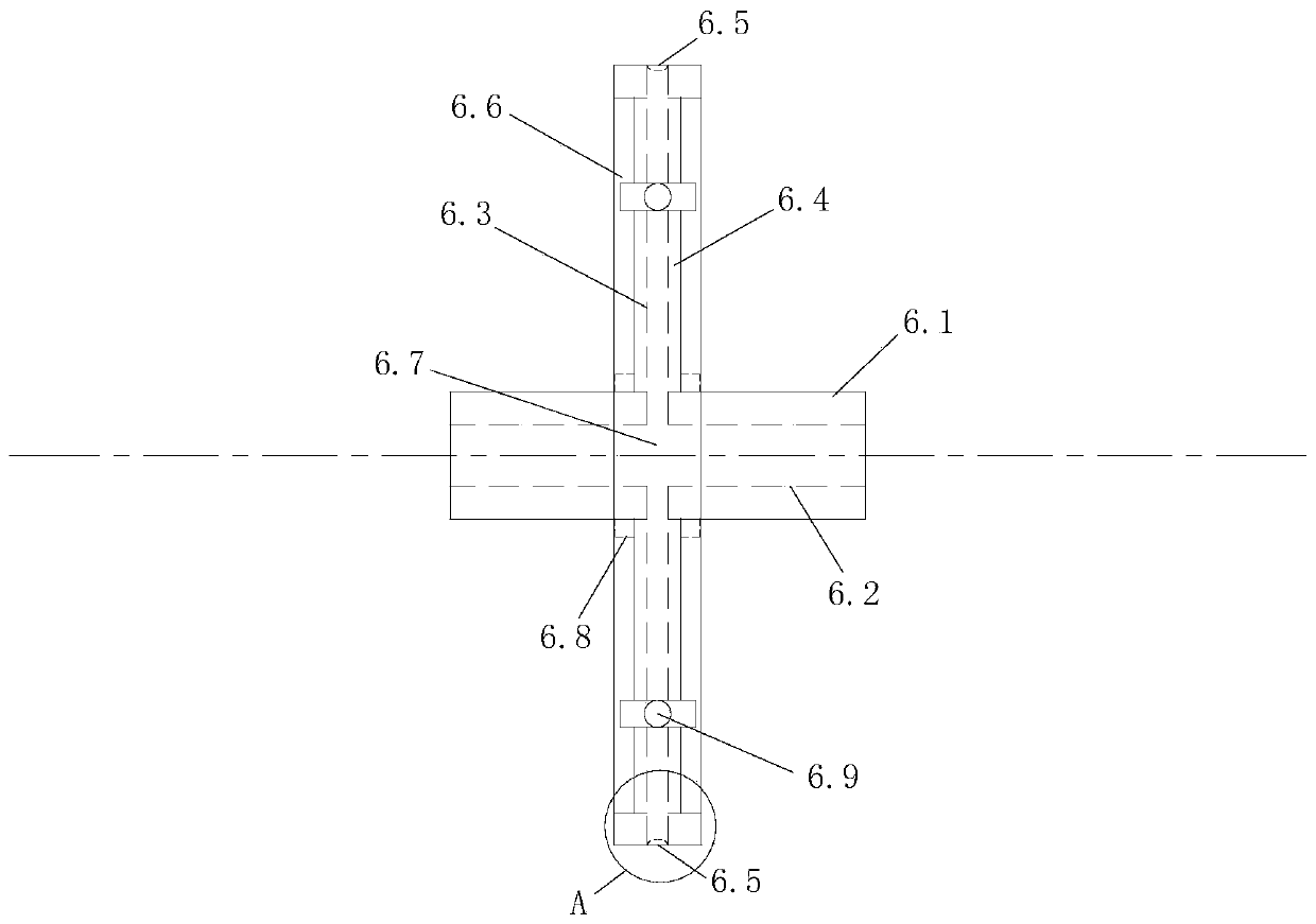
[0110] Referring to the accompanying drawings, it can be seen that the hydraulic cutting tool module includes a hydraulic cutting tool module frame 1, a thrust spring structure 2, a hydraulic cutting tool module thrust cylinder 3, a hydraulic cutting tool module guiding connection cylinder 4, a fixing seat 5 and the combined rock breaking The hydraulic cutting hob 6;

[0111] The fixed ends of the hydraulic cutting tool module thrust cylinder 3 and the hydraulic cutting tool module guiding connection cylinder 4 are all fixed on the fixed seat 5;

[0112] The thrust spring structure 2 is located in the hydraulic cutting tool module frame 1;...


PUM


Abstract

The invention discloses a hydraulic cutting tool module. The hydraulic cutting tool module comprises a hydraulic cutting tool module frame, a thrust spring structure, a hydraulic cutting tool module thrust oil cylinder and a hydraulic cutting hob for combined rock breaking, wherein the thrust spring structure is located in the hydraulic cutting tool module frame, the hydraulic cutting tool modulethrust oil cylinder is located at the upper end of the thrust spring structure, and the hydraulic cutting hob for combined rock breaking is fixed to the lower end of the hydraulic cutting tool moduleframe and is of a spoke structure. The hydraulic cutting tool module has the advantages that the weight of the hob is reduced through lightweight treatment, and the rock breaking efficiency is improved. The invention further discloses a hydraulic-mechanical combined rock breaking TBM device. The invention further discloses a rock breaking method of the hydraulic-mechanical combined rock breaking TBM device.

Description


Claims


Application Information

Patent Timeline
Owner INST OF ROCK AND SOIL MECHANICS - CHINESE ACAD OF SCI
Why Eureka
Try Eureka