
A Creep Correction Method for Load Cell

A load cell and creep technology, applied in the field of electronic scales, can solve the problems of high manufacturing process requirements, inaccurate correction, and high manufacturing cost of load cells, meet the needs of high-precision measurement, improve applicability, and avoid deviations Effect

Active Publication Date: 2022-02-22
VATTI CORP LTD
View PDF8 Cites 0 Cited by
  • Summary
  • Abstract
  • Description
  • Claims
  • Application Information

AI Technical Summary

Problems solved by technology

[0004] However, the above scheme 1 has high requirements on the manufacturing process of the load cell, the manufacturing cost is high, and there is a certain deviation between the same batch of sensors, so that the manufactured creep compensation sheet may not be suitable for every sensor, resulting in the creep compensation sheet The correction is not accurate. Although Plan 2 can automatically correct according to the creep characteristics of the electronic scale body, it increases the calibration time and complexity. If the load cell is used in kitchen appliances, such as steamers, ovens and other high-temperature and high-humidity environments In this case, there may be a large error between the actual creep curve and the creep curve model used, resulting in inaccurate correction

Method used


Image

  • A Creep Correction Method for Load Cell
  • A Creep Correction Method for Load Cell
  • A Creep Correction Method for Load Cell

Examples


Embodiment 1

[0050] In this embodiment, the electronic scale adopts the following parameters to set T=500ms, a=40, X=10, m=100.

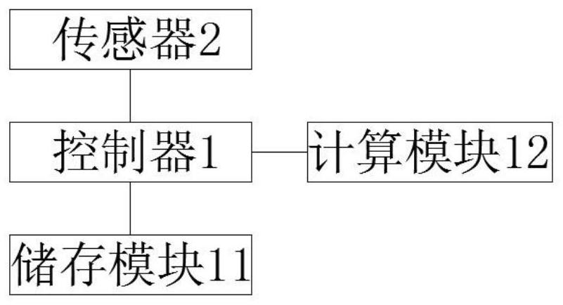
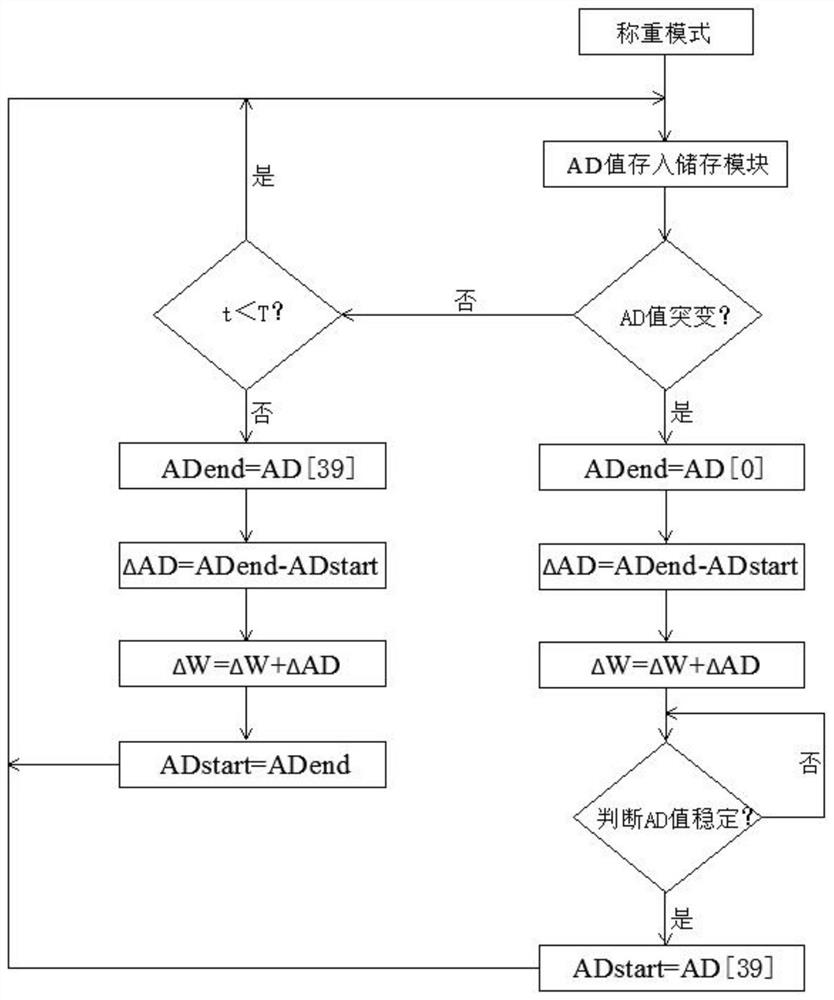
[0051] Then in the stable mode, the controller 1 will detect the AD value 40 times at intervals of 500ms, and the sensor 2 can be recorded as AD[0], AD[1]...AD[39] according to the recording sequence.

[0052] When the controller 1 judges stable, the controller 1 sets the sensor 2 at T trig The bth AD value measured in the time period is recorded as T trig AD[b], first determine whether the b-1th AD value measured by sensor 2 is stable compared with the bth AD value, AD temp =T trig AD[b]-T trig AD[b-1], if AD is judged temp ≥10, it is judged that the AD value is unstable at this time, and the number of judgments Y is recorded as 0, that is, Y=0; if it is judged that AD temp <10, it is determined that the AD value is stable at this time, and the number of times Y is added to Y=Y+1. When the number of times Y≥100, it is determined that the AD value has stabi...

Embodiment 2

[0055] In this embodiment, the electronic scale does not use any creep correction method, and in an environment with a temperature of 25°C and a humidity of 60%, several measurements are made on a 165g object. The measurement results are as follows: Figure 5 Shown in curve b.

[0056] It can be seen from the figure that curve b will change with time, and will gradually move up when weighing the same item. Compared with curve a and curve b, curve a is processed by creep correction method, and the weight value is stable. There will be no problem that the weight value rises with time, and the measurement error caused by the creep of the load cell 2 itself is well solved to ensure the measurement accuracy.


PUM


Abstract

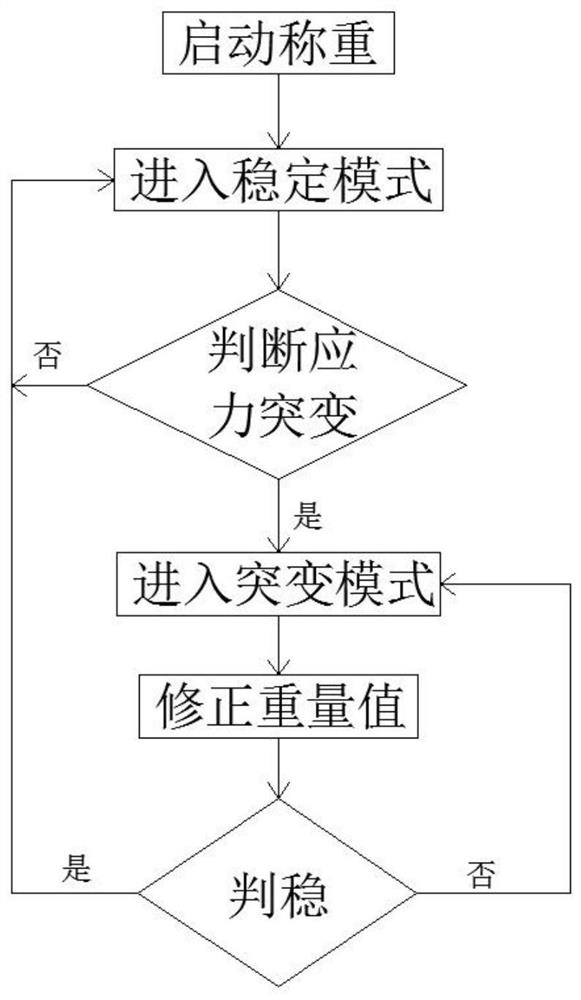
The invention relates to a creep correction method of a load cell, which comprises the following steps: the load cell starts weighing, enters a stable mode, and calculates the creep value; determines whether the AD value has a sudden change; enters the sudden change mode, and sends out a stable judgment command; after the stability judgment is over, enter the stable mode and calculate the creep value. The above-mentioned creep correction method does not depend on the static creep amount and time curve model, but realizes dynamic creep correction for the weighing process, avoids the deviation between the judgment curve model and the actual curve, greatly improves the applicability, and is suitable for kitchen appliances ;In the process of adding or subtracting heavy objects, the stress changes and the deformation becomes unstable. Therefore, in the sudden change mode, stop accumulating the total amount of creep, filter the uncertain creep value, and avoid calculation deviation.

Description

technical field [0001] The invention relates to the technical field of electronic scales, in particular to a creep correction method for a load cell. Background technique [0002] Creep, as a main technical indicator for detecting sensor performance, refers to the phenomenon that the strain of solid materials increases with time under the condition of keeping the stress constant. Currently common electronic weighing tools on the market, such as kitchen scales, weighing scales, etc., the load cell used inside is composed of metal elastic body and strain gauge, and the metal material will show creep under the condition of keeping the stress constant. Variable characteristics, that is, the amount of strain increases with time. [0003] In order to overcome the measurement error caused by the creep of the load cell itself, the following two solutions are commonly used: 1. From the hardware process level, use creep compensation sheets to compensate or improve the thickness of th...

Claims


Application Information

Patent Timeline
Patent Type & Authority Patents(China)
IPC IPC(8): G01G23/01
CPCG01G23/01
Inventor 罗淦恩潘叶江
Owner VATTI CORP LTD
Learn More