Optical axis offset compensation method and device

An optical axis offset and compensation method technology, which is applied in the parts and electrical components of TVs and color TVs, can solve the problems of high implementation cost of optical axis offset compensation and extremely high requirements for control accuracy of the pan/tilt system. The effect of reducing the cost of realization, the difficulty of realization, and the cost of realization

Active Publication Date: 2020-03-03
ZHEJIANG UNIVIEW TECH
View PDF7 Cites 9 Cited by
  • Summary
  • Abstract
  • Description
  • Claims
  • Application Information

AI Technical Summary

Problems solved by technology

However, this optical axis offset compensation method has extremely high requirements on the control accuracy of the pan/tilt system, and the implementation cost of optical axis offset compens

Method used


Image

  • Optical axis offset compensation method and device
  • Optical axis offset compensation method and device
  • Optical axis offset compensation method and device

Examples


Embodiment Construction

[0029] In order to make the purpose, technical solutions and advantages of the embodiments of the present invention clearer, the technical solutions in the embodiments of the present invention will be clearly and completely described below in conjunction with the drawings in the embodiments of the present invention. Obviously, the described embodiments It is a part of embodiments of the present invention, but not all embodiments. The components of the embodiments of the invention generally described and illustrated in the figures herein may be arranged and designed in a variety of different configurations.

[0030] Accordingly, the following detailed description of the embodiments of the invention provided in the accompanying drawings is not intended to limit the scope of the claimed invention, but merely represents selected embodiments of the invention. Based on the embodiments of the present invention, all other embodiments obtained by persons of ordinary skill in the art wi...


PUM


Abstract

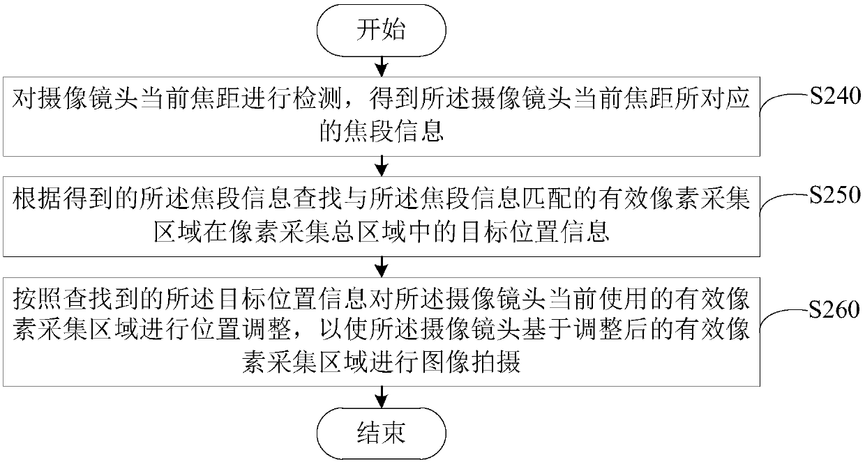
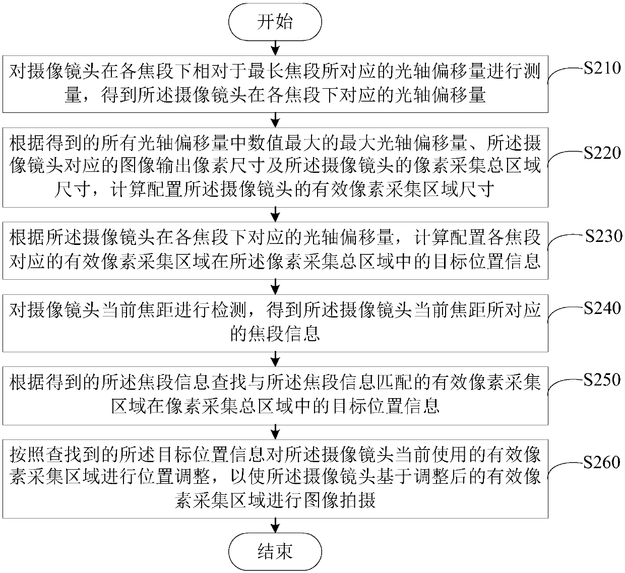
The invention provides an optical axis offset compensation method and an optical axis offset compensation device, which are applied to camera equipment comprising a camera lens. The method comprises the following steps: detecting the current focal length of the camera lens to obtain focal length range information corresponding to the current focal length of the camera lens; searching target position information of the effective pixel collection area matched with the focal segment information in the pixel collection total area according to the obtained focal length range information; and adjusting the position of an effective pixel collection area currently used by the camera lens according to the searched target position information, so that the camera lens performs image shooting based onthe adjusted effective pixel collection area. According to the method, the optical axis offset of the camera lens can be accurately corrected by adopting an electronic compensation mode with low implementation difficulty, and the optical axis offset compensation implementation cost is reduced.

Description

technical field [0001] The invention relates to the technical field of security monitoring, in particular to an optical axis offset compensation method and device. Background technique [0002] The camera equipment used in the field of security monitoring generally has the zoom function of the lens. However, due to the inevitable design errors and production accuracy errors in the design and manufacturing process of the lens, most of the lenses will have optical axis deviation during the process of zooming. Shifting phenomenon, that is, the target at the center of the screen at a certain magnification becomes larger or smaller after the magnification of the lens becomes larger or smaller, and the target that was originally at the center of the screen is no longer at the center of the screen corresponding to the adjusted magnification, but There is a positional shift in a certain direction. [0003] The phenomenon of optical axis deviation usually causes the lens to be unabl...

Claims


Application Information

Patent Timeline
IPC IPC(8): H04N5/232
CPCH04N23/67H04N23/69
Inventor 李宇翔
Owner ZHEJIANG UNIVIEW TECH
Why Eureka
Try Eureka