
Welding clamp for welding of printed circuit board

A technology for printed circuit boards and welding fixtures, which is applied in the direction of printed circuits, welding equipment, auxiliary welding equipment, etc., can solve the problems of not being able to adjust the rotation freely, the circuit board is easy to shake, and the clamping is not firm enough to achieve simple structure and clamping Stable and convenient clamping and loosening effect

Inactive Publication Date: 2020-03-06
江苏金桥玻璃科技有限公司
View PDF0 Cites 0 Cited by
  • Summary
  • Abstract
  • Description
  • Claims
  • Application Information

AI Technical Summary

Problems solved by technology

[0002] The welding jig for printed circuit board welding is a jig used to stably clamp the circuit board for easy welding. Although the current welding jig does a good job in heat dissipation, the circuit board is easy to shake during the welding process, and the clamping is not firm enough. And it cannot be freely adjusted and rotated according to the size and direction of the circuit board. Therefore, we propose a welding fixture for printed circuit board welding

Method used


Image

  • Welding clamp for welding of printed circuit board

Examples


Embodiment Construction

[0013] The following will clearly and completely describe the technical solutions in the embodiments of the present invention with reference to the accompanying drawings in the embodiments of the present invention. Obviously, the described embodiments are only some, not all, embodiments of the present invention. Based on the embodiments of the present invention, all other embodiments obtained by persons of ordinary skill in the art without making creative efforts belong to the protection scope of the present invention.

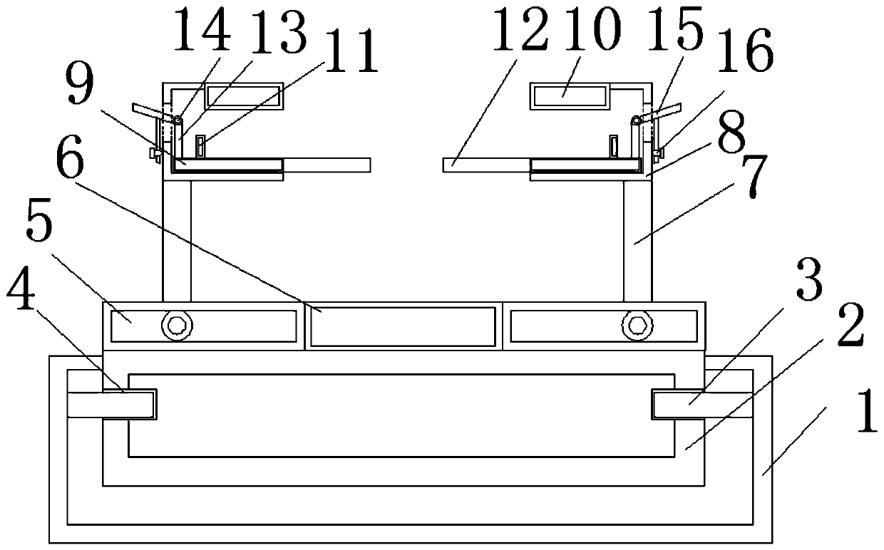
[0014] see figure 1 , the present invention provides a technical solution: a welding fixture for printed circuit board welding, including an annular base 1, an annular turntable 2 is installed in the inner cavity of the annular base 1, an annular bump 3 is arranged in the inner cavity of the annular base 1, and an annular turntable 2 A groove 4 matching the annular bump 3 is provided in the inner cavity, sliding devices 5 are installed on the left and right si...


PUM


Abstract

The invention discloses a welding clamp for welding of a printed circuit board. The welding clamp for welding of the printed circuit board comprises a ring-shaped pedestal; a ring-shaped turnplate isarranged in an inner cavity of the ring-shaped pedestal; a ring-shaped convex block is arranged in the inner cavity of the ring-shaped pedestal; a groove matched with the ring-shaped convex block is formed in the inner cavity of the ring-shaped turnplate; sliding devices are arranged on the left side and the right side of the top of the ring-shaped turnplate; a fixed block is arranged between thetwo groups of sliding devices; supporting rods are arranged at the tops of the two groups of sliding devices; clamp brackets are arranged at the tops of the two groups of supporting rods; lower clamping blocks are arranged at the bottoms of inner cavities of the two groups of clamp brackets; upper clamping blocks are arranged at the tops of the clamp brackets; the sliding devices are provided, sothe length can be adjusted freely; fixed rods are provided and connected with the lower clamping blocks and movable rods drive the fixed rods and the lower clamping blocks to ascend, so that the circuit board can be clamped and fit conveniently; and the welding clamp for welding of the printed circuit board has a simple structure, can adjust the length direction freely, is stable to clamp and is convenient to clamp and loosen.

Description

technical field [0001] The invention relates to the technical field of fixtures, in particular to a welding fixture for welding printed circuit boards. Background technique [0002] The welding jig for printed circuit board welding is a jig used to stably clamp the circuit board for easy welding. Although the current welding jig does a good job in heat dissipation, the circuit board is easy to shake during the welding process, and the clamping is not firm enough. Moreover, the rotation cannot be freely adjusted according to the size and direction of the circuit board. Therefore, we propose a welding fixture for printed circuit board welding. Contents of the invention [0003] The object of the present invention is to provide a soldering jig for soldering printed circuit boards, so as to solve the problems raised in the above-mentioned background technology. [0004] In order to achieve the above object, the present invention provides the following technical solutions: a w...

Claims


Application Information

Patent Timeline
Patent Type & Authority Applications(China)
IPC IPC(8): B23K3/08B23K37/04B23K101/42
CPCB23K3/087B23K2101/42
Inventor 李开兰
Owner 江苏金桥玻璃科技有限公司
Learn More