
Power battery cooling and heating integrated system and batteries

A power battery and integrated system technology, applied in the field of new energy vehicle batteries, can solve the problems of poor reliability, low heat utilization rate and short service life, and achieve good heating and cooling effect, high heat utilization rate and long service life. Effect

Pending Publication Date: 2017-05-10
SHENZHEN SHARING ELECTRONICS
View PDF8 Cites 5 Cited by
  • Summary
  • Abstract
  • Description
  • Claims
  • Application Information

AI Technical Summary

Problems solved by technology

[0011] The present invention proposes a power battery cooling and heating integrated system, which solves the existing problems of single function, short service life, poor reliability, poor cooling effect, low heat utilization rate, large energy consumption, low integration and inconvenient problems existing in the prior art. technical problem

Method used


Image

  • Power battery cooling and heating integrated system and batteries
  • Power battery cooling and heating integrated system and batteries
  • Power battery cooling and heating integrated system and batteries

Examples


Embodiment 1

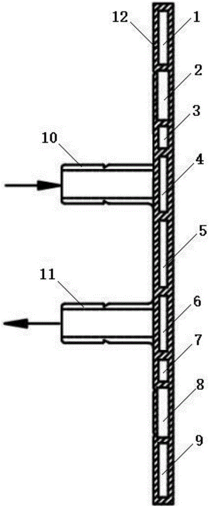
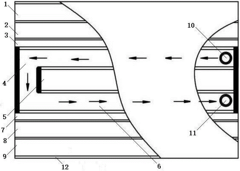
[0052] Such as Figure 1-3 , Figure 12A power battery cooling and heating integrated system is shown, including a coolant tank, a circulation pump and a radiator, the coolant tank is connected to the circulation pump, the circulation pump is connected to the radiator, one end of the battery pack heating and cooling integrated board is connected to the radiator, and the battery pack is heated The other end of the cooling integrated board is connected to the coolant tank; the heating and cooling integrated board of the battery pack includes a first PTC heating cavity 1, a second PTC heating cavity 2, a first heat insulation cavity 3, a first Coolant cavity 4, cavity 5, second coolant cavity 6, second heat insulation cavity 7, third PTC heating cavity 8, fourth PTC heating cavity 9, coolant inlet joint 10 and coolant outlet Connector 11, the first PTC heating cavity 1 is connected to the second PTC heating cavity 2, the second PTC heating cavity 2 is connected to the first heat...

Embodiment 2

[0054] Such as Figure 4 As shown, on the basis of Example 1, the first cooling liquid cavity 4 and the second cooling liquid cavity 6 are changed in parallel to set up dual channels. The dual-channel cooling liquid cavity doubles the refrigeration rate, and the channels are changed according to requirements. Quantity, adjust cooling power.

Embodiment 3

[0056] Such as Figure 5-7 As shown, a first PTC heating cavity 1, a second PTC heating cavity 2, a first heat insulation cavity 3, a first cooling liquid cavity 4, a cavity 5, and a second cooling liquid cavity are provided on the heat conducting substrate 12 6. The second heat insulation cavity 7, the third PTC heating cavity 8, the fourth PTC heating cavity 9, the coolant inlet connector 10 and the coolant outlet connector 11, the first PTC heating cavity 1 is connected to the second PTC heating cavity Body 2, the second PTC heating cavity 2 is connected to the first heat insulation cavity 3, the first heat insulation cavity 3 is connected to the first cooling liquid cavity 4, the first cooling liquid cavity 4 is connected to the cavity 5, and the cavity 5 is connected to the second Two cooling liquid chambers 6, the second cooling liquid chamber 6 is connected to the second heat insulating chamber 7, the second heat insulating chamber 7 is connected to the third PTC heatin...


PUM


Abstract

The invention relates to a power battery cooling and heating integrated system, which comprises a cooling liquid tank, a circulating pump, a radiator and a battery pack heating and cooling integrated board, wherein the cooling liquid tank is connected with the circulating pump; the circulating pump is connected with the radiator; and one end of the battery pack heating and cooling integrated board is connected with the radiator and the other end of the battery pack heating and cooling integrated board is connected with the cooling liquid tank. The power battery cooling and heating integrated system has the advantages that one set of substrate is shared by a heating system and a cooling system, the power battery cooling and heating integrated system is long in service life, good in stability, good in heating and cooling effects, high in integration level, convenient to use and high in heat utilization rate, and the power is saved.

Description

technical field [0001] The invention relates to the field of new energy vehicle batteries, in particular to a power battery cooling and heating integrated system and the battery. Background technique [0002] The heating principle of the existing power battery heating system: start the water pump and the PTC heater, the coolant passes through the water pump, the PTC heater, the liquid cooling plate, and the coolant tank for circulation heating, and the heated coolant transfers heat to the water cooling plate, The liquid cold plate then transfers the heat to the power battery. [0003] This kind of heating system has the following disadvantages: During the heating process, it is necessary to heat the refrigerant tank, pipeline, PTC heater and the coolant in the PTC heater, and the whole system has a long circulating water path, and the heat dissipation pump must also work. It consumes a lot of useless heat, and the utilization rate of electric energy is low; especially when ...

Claims


Application Information

Patent Timeline
Patent Type & Authority Applications(China)
IPC IPC(8): H01M10/613H01M10/615H01M10/625H01M10/6556H01M10/6567H01M10/6571
CPCH01M10/613H01M10/615H01M10/625H01M10/6556H01M10/6567H01M10/6571Y02E60/10
Inventor 吴翔闻俊涛鄂新刚
Owner SHENZHEN SHARING ELECTRONICS
Learn More