
Array substrate, display panel and display device

An array substrate and display panel technology, which is applied in instruments, computing, optics, etc., can solve the problems affecting the uniformity of the backlight of the backlight module and the display effect of the liquid crystal display, so as to reduce the thickness, quickly and accurately identify, improve the efficiency and The effect of accuracy

Inactive Publication Date: 2020-03-06
SHANGHAI TIANMA MICRO ELECTRONICS CO LTD
View PDF14 Cites 5 Cited by
  • Summary
  • Abstract
  • Description
  • Claims
  • Application Information

AI Technical Summary

Problems solved by technology

This setting will affect the uniformity of the backlight provided by the backlight module, thereby affecting the display effect of the LCD

Method used


Image

  • Array substrate, display panel and display device
  • Array substrate, display panel and display device
  • Array substrate, display panel and display device

Examples


Embodiment Construction

[0029] The specific implementation manners of an array substrate, a display panel and a display device provided by the embodiments of the present invention will be described in detail below with reference to the accompanying drawings. It should be noted that the described embodiments are only some of the embodiments of the present invention, but not all of the embodiments. Based on the embodiments of the present invention, all other embodiments obtained by persons of ordinary skill in the art without making creative efforts belong to the protection scope of the present invention.

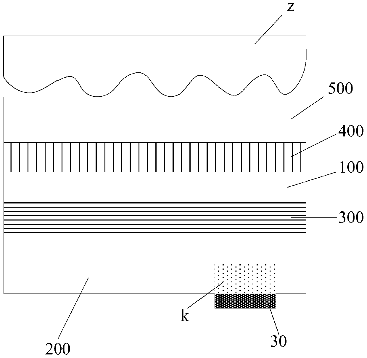
[0030] The inventor found in the research that for a liquid crystal display provided with a fingerprint identification structure, the specific structure can be as follows: figure 1 As shown, the figure shows a backlight module 200, a lower polarizer 300, a display panel 100, an upper polarizer 400, a cover plate 500, and a fingerprint recognition structure 30; On one side of the display panel 100, ...


PUM


Abstract

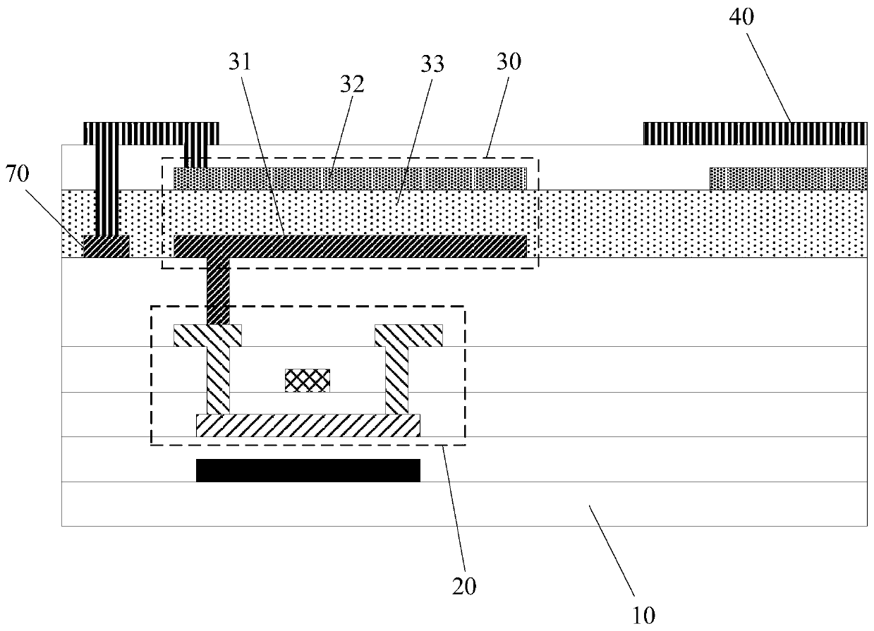
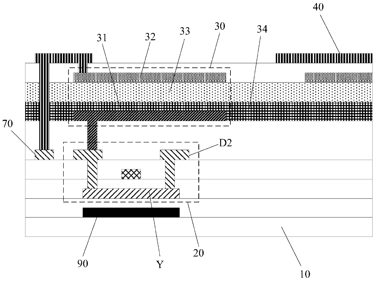
The invention discloses an array substrate, a display panel and a display device. According to the invention, a fingerprint identification structure is arranged in the array substrate, and is not arranged at one side, far away from the display panel, of a backlight module in the prior art, so that in the embodiment of the invention, the backlight module does not need to be specially designed (suchas trepanning), the fingerprint identification device does not cause adverse effects on the uniformity of a backlight source provided by the backlight module, and the normal display of the display device can be ensured; and moreover, the embedded design of the fingerprint identification structure is realized, so that the thickness of the display device can be reduced, and the light and thin design is achieved while a fingerprint identification function is achieved. In addition, in the fingerprint identification process, the fingerprint identification device is closer to a fingerprint, and a signal received by the fingerprint identification device is stronger, so that the fingerprint identification device can perform identification quickly and accurately, and the efficiency and accuracy offingerprint identification are improved.

Description

technical field [0001] The invention relates to the field of display technology, in particular to an array substrate, a display panel and a display device. Background technique [0002] A liquid crystal display is a non-self-luminous device, which requires a backlight module, and uses the backlight provided by the backlight module to realize the display function. For liquid crystal displays, if the fingerprint recognition function is to be realized, a fingerprint recognition device needs to be installed, and in the current technology, the fingerprint recognition device is generally arranged on the side of the non-light-emitting surface of the backlight module, that is, the fingerprint recognition device is arranged on the backlight module. The side facing away from the display panel. [0003] However, in order to realize the fingerprint recognition function, openings need to be provided in the backlight module, so that the light reflected by the fingerprint can be incident ...

Claims


Application Information

Patent Timeline
Patent Type & Authority Applications(China)
IPC IPC(8): G02F1/13357G06K9/00
CPCG02F1/133602G02F1/13362G06F18/00
Inventor 袁永
Owner SHANGHAI TIANMA MICRO ELECTRONICS CO LTD
Learn More