Telescopic rod for installing knob of electric appliance

A telescopic rod and knob technology is applied in the field of electrical knob auxiliary structures, which can solve the problems of easy accidental touches and affect the aesthetics of electrical appliances, and achieve the effects of improving efficiency, convenient and quick use and replacement, and convenient and quick use.

Pending Publication Date: 2020-03-06
上海科聚精密塑料有限公司
View PDF1 Cites 0 Cited by
  • Summary
  • Abstract
  • Description
  • Claims
  • Application Information

AI Technical Summary

Problems solved by technology

[0004] The utility model published in the above application documents increases the structural strength of the rotary installation by setting two knobs, the inner and the outer, and the positioning effect between the inner knob, the knob seat and the valve stem sleeve is good, and it is not easy to be misplaced, but in the actual use process Among them, this design method, because the knob is protruding and the knob seat is installed, not only affects the aesthetics of the electrical appliance, but also is prone to accidental touches

Method used


Image

  • Telescopic rod for installing knob of electric appliance
  • Telescopic rod for installing knob of electric appliance
  • Telescopic rod for installing knob of electric appliance

Examples


Embodiment Construction

[0033] The present invention will be described in further detail below in conjunction with the accompanying drawings.

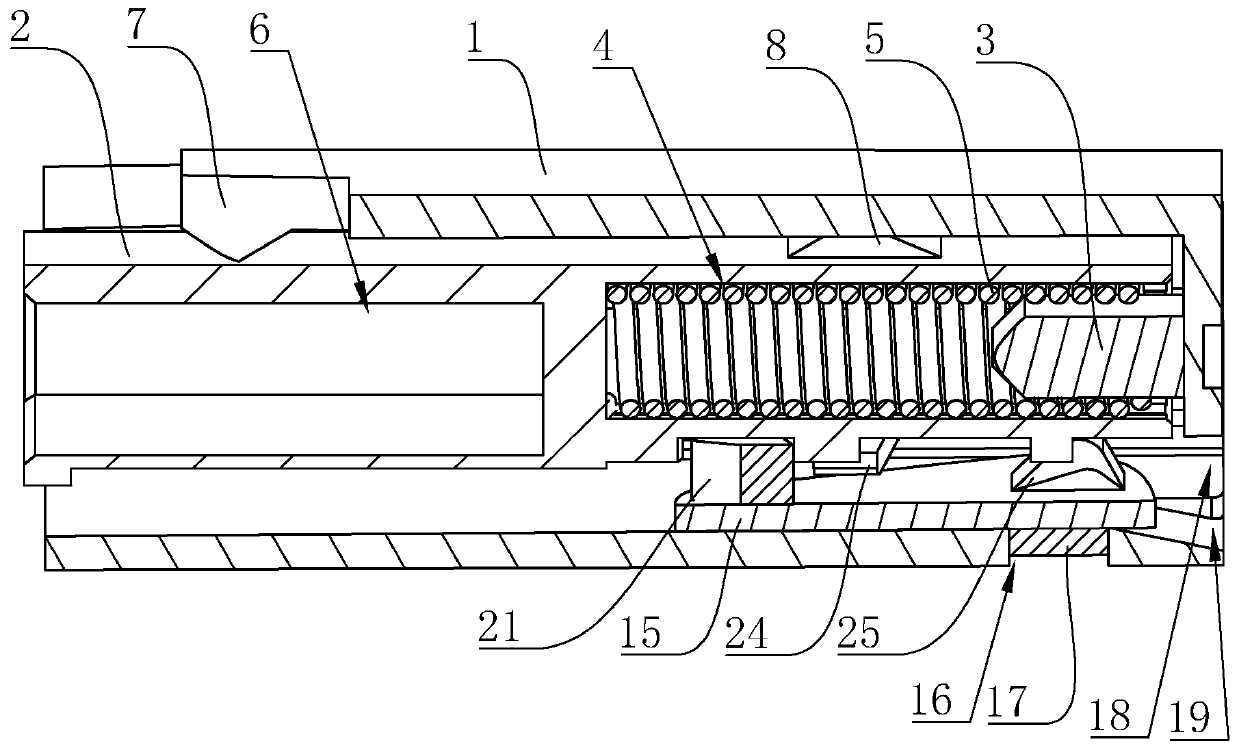
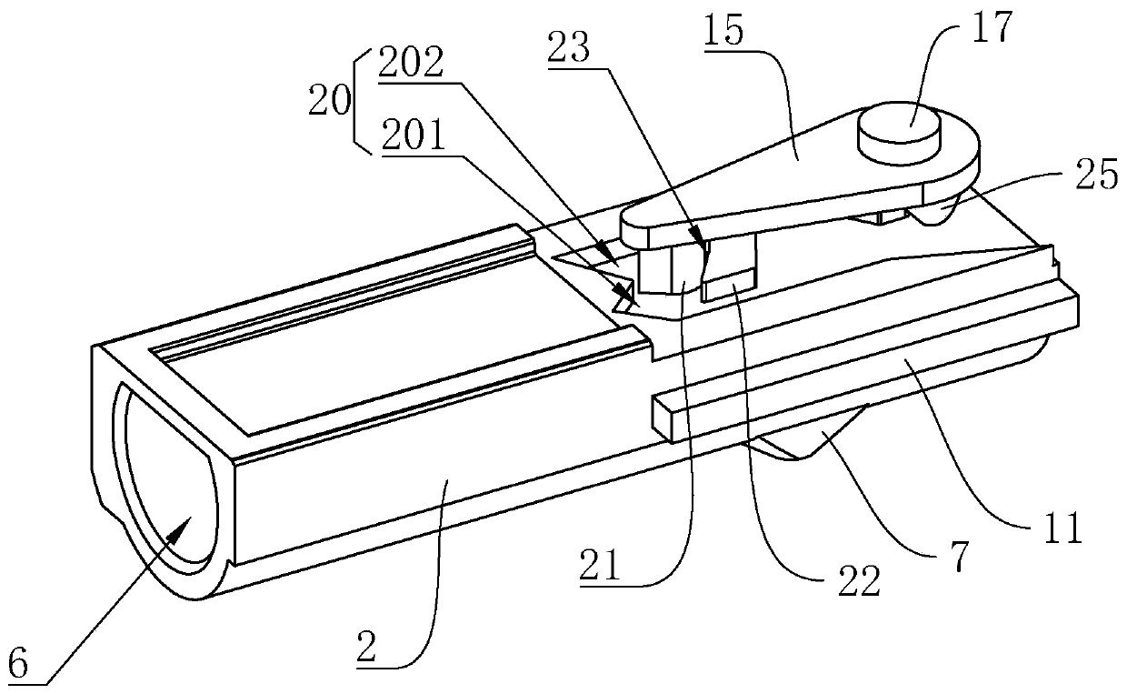
[0034] refer to figure 1 and figure 2 As shown, it is a telescoping rod for installing electrical knobs disclosed by the present invention, which includes a semi-cylindrical outer fixing cylinder 1, the outer fixing cylinder 1 is a structure with one end open and one end closed, and the outer fixing cylinder 1 is equipped with a The inner telescopic column 2 that is slidably matched. The outer fixing cylinder 1 is integrally formed with a cylindrical plug-in column 3 close to its closed end, and the end of the inner telescopic column 2 close to the plug-in column 3 is provided with a circular plug-in groove 4, and the plug-in column 3 is connected to the plug-in socket. The cylinder is coaxially arranged, and a spring 5 is installed between the closed end of the outer fixed cylinder 1 and the inner telescopic column 2, one end of the spring 5 is sleeved on...


PUM


Abstract

The invention relates to a telescopic rod for installing a knob of an electric appliance. The telescopic rod comprises an outer fixed cylinder with at least one edge, and an inner telescopic column isslidably mounted in the outer fixed cylinder; the closed end of the outer fixed cylinder abuts against the inner telescopic column through a spring. A limiting clamping block is arranged on the outerside wall of the inner telescopic column; an elastic buckle clamped with the limiting clamping block is arranged at the position, close to the opening, of the outer fixed cylinder; a mounting groovefor mounting an external knob is formed in one end, away from the spring, of the inner telescopic column; a sliding groove is formed in the outer side wall of the inner telescopic column; the slidinggroove comprises a pressing groove and a springback groove, an abutting block is arranged on the outer side wall of the inner telescopic column, the abutting block is located between the pressing groove and the springback groove, a clamping groove is formed in the end, close to the mounting groove, of the abutting block, a swing hook is rotationally mounted on the inner side wall of the outer fixing cylinder, and a clamping block clamped with the clamping groove is arranged on the swing hook. The knob on the electric appliance can be placed in the electric appliance, so the electric applianceis more attractive, and the knob is prevented from being touched by mistake.

Description

technical field [0001] The invention relates to the technical field of an auxiliary structure of an electrical appliance knob, in particular to a telescopic rod for installing an electrical appliance knob. Background technique [0002] In the existing electrical appliances with knobs, the knobs are usually exposed outside the electrical appliances. This design is convenient for adjusting the electrical appliances by turning the knobs. [0003] In the Chinese utility model patent with the application number CN201821184095.7, a rotary button in an oven is disclosed, including an outer knob, an inner knob, a light-emitting circuit board, a knob seat, a valve stem cover and an LED lamp. In the outer knob, the LED light is fixed on the inner knob, and the LED light is connected to the light-emitting circuit board. The light-emitting circuit board is fixed in the knob seat through pins, and the inner knob is inserted into the knob seat, and one end of the inner knob passes through...

Claims


Application Information

Patent Timeline
Patent Type & Authority Applications(China)
IPC IPC(8): G05G1/12F16B7/10
CPCF16B7/10G05G1/12
Inventor 沈灏
Owner 上海科聚精密塑料有限公司
Why Eureka
Try Eureka