Photovoltaic tracking support

A photovoltaic and pillar technology, applied in the support structure of photovoltaic modules, photovoltaic modules, photovoltaic power generation and other directions, can solve the problems of rusting of the connection position, wrong angle adjustment, accumulation of dust particles, etc., and achieve the effect of reducing blockage

Inactive Publication Date: 2021-12-31
郑有真
View PDF0 Cites 0 Cited by
  • Summary
  • Abstract
  • Description
  • Claims
  • Application Information

AI Technical Summary

Problems solved by technology

[0004] The purpose of the present invention is to provide a photovoltaic tracking bracket to solve the problem that most of the existing photovoltaic brackets are equipped with an angle adjustment device. When the angle adjustment of the bracket is performed in rainy days, the rainwater will flow into the support along the main beam. Due to the dust particles carried in the rainwater and the rainwater leaks to the angle adjustment position, it is easy to rust the connection position or accumulate a large amount of dust particles, resulting in angle adjustment errors or even accidental stuck technical problems.

Method used


Image

  • Photovoltaic tracking support
  • Photovoltaic tracking support
  • Photovoltaic tracking support

Examples


Embodiment

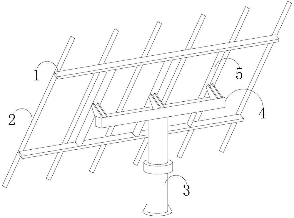
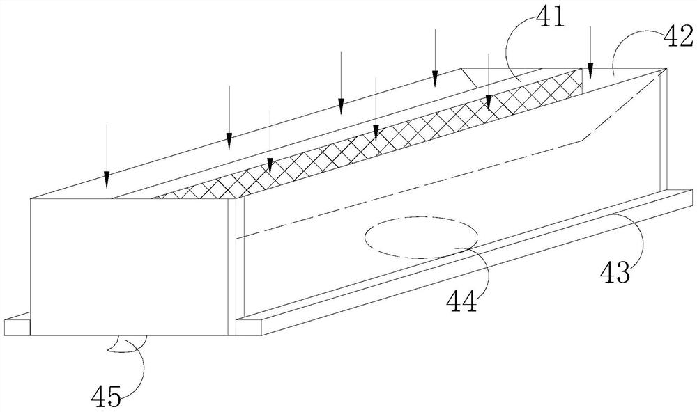
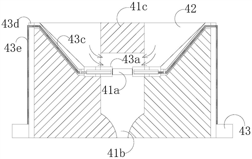
[0027] Such as Figure 1-Figure 6 As shown, the present invention provides a photovoltaic tracking bracket, the structure of which includes a fixed crossbar 1, a mounting frame 2, a pillar 3, a main beam 4, and a connecting shaft 5, the main beam 4 is mechanically connected to the pillar 3, and the mounting frame 2. There are more than two. The lateral position of the mounting frame 2 is fixed by the fixed cross bar 1, and the fixed cross bar 1 is connected with the connecting shaft 5, and the connecting shaft 5 is fixedly connected with the main beam 4. The main beam 4 is provided with a partition device 41, a water guide 42, a movable scraper 43, a rotating base 44, and a water outlet 45. The water guide 42 is provided with two, and the water guide 42 is separated by a partition device 41. The main beam 4 is movably connected with the pillar 3 through the rotating base 44, the movable scraper 43 is arranged on the left and right outer sides of the main beam 4, the water outl...


PUM


Abstract

The invention discloses a photovoltaic tracking support which structurally comprises fixing transverse rods, more than two mounting frames, a supporting column, a main beam and a connecting shaft. The main beam is mechanically connected with the supporting column, the transverse positions of the mounting frames are fixed through the fixing transverse rods, the fixing transverse rods are connected through the connecting shaft, and the connecting shaft is fixedly connected with the main beam. The main beam is provided with a partition plate device, a water guide groove, a movable scraper blade, a rotating base and a water outlet. The water guide groove is formed in the main beam and is of a right trapezoid structure, that is, the side, facing the partition plate device, of the water guide groove is of a plane type, and the other side of the water guide groove is of an inclined plane type, so that rainwater falling on the main beam can be effectively guided out from the water outlet through the water guide groove in a rainy environment; it is guaranteed that no rainwater remains on the whole upper end plane of the main beam and does not flow to the rotating base along the whole main beam.

Description

technical field [0001] The invention relates to the field of photovoltaic components, in particular, it is a photovoltaic tracking bracket. Background technique [0002] Photovoltaic panel module bracket is a power generation device that generates direct current when exposed to sunlight. It is composed of thin solid photovoltaic cells almost entirely made of semiconductor materials. Photovoltaic panel modules are usually installed and fixed with photovoltaic brackets during use , to meet the needs of users. [0003] In order to maximize the utilization of light energy in the photovoltaic system, most of the existing photovoltaic supports are equipped with angle adjustment devices. When the angle of the support is adjusted in rainy days, the rainwater will flow along the main beam into the rotating joint with the support. Because the rainwater carries dust particles and the rainwater seeps into the angle adjustment position, it is easy to rust the connection position or accu...

Claims


Application Information

Patent Timeline
Patent Type & Authority Applications(China)
IPC IPC(8): H02S20/32H02S40/10F24S25/60B01D46/10B01D46/00
CPCH02S20/32H02S40/10F24S25/60B01D46/10Y02E10/47Y02E10/50
Inventor 郑有真
Owner 郑有真
Why Eureka
Try Eureka