Radiating structure of electronic assemblies

A technology for electronic components and heat dissipation structures, which can be used in lighting and heating equipment, cooling/ventilation/heating renovation, semiconductor devices of light-emitting elements, etc.

Active Publication Date: 2010-03-17
DONG GUAN HAN XU HARDWARE & PLASTIC TECH CO LTD
View PDF3 Cites 6 Cited by
  • Summary
  • Abstract
  • Description
  • Claims
  • Application Information

AI Technical Summary

Problems solved by technology

The main purpose of the present invention is: the aluminum heat sink system on the heat dissipation structure is connected with a heat dissipation fin, and the aluminum heat sink body is provided with at least one copper column for heat conduction by means of mold closing and forcing. The body is arranged on it, and several electronic components are respectively arranged on the relative positions of the copper pillar heat conductors, so that when the electronic components start to operate and generate heat energy, through the relative position of the copper pillar heat conductors Setting, effectively exporting heat quickly, with the above-mentioned technology, it can be aimed at the improvement of the heat dissipation module of conventional LED lamps. The existing heat dissipation method is that it is necessary to punch holes on the aluminum heat dissipation base to form a concave hole, and then Then put the heat-conducting copper pillar into the concave hole. This method is not only time-consuming and labor-intensive, but also not cost-effective. There is an additional concave ho

Method used


Image

  • Radiating structure of electronic assemblies
  • Radiating structure of electronic assemblies
  • Radiating structure of electronic assemblies

Examples


Embodiment Construction

[0024] The present invention will be further described below in conjunction with the accompanying drawings and specific embodiments.

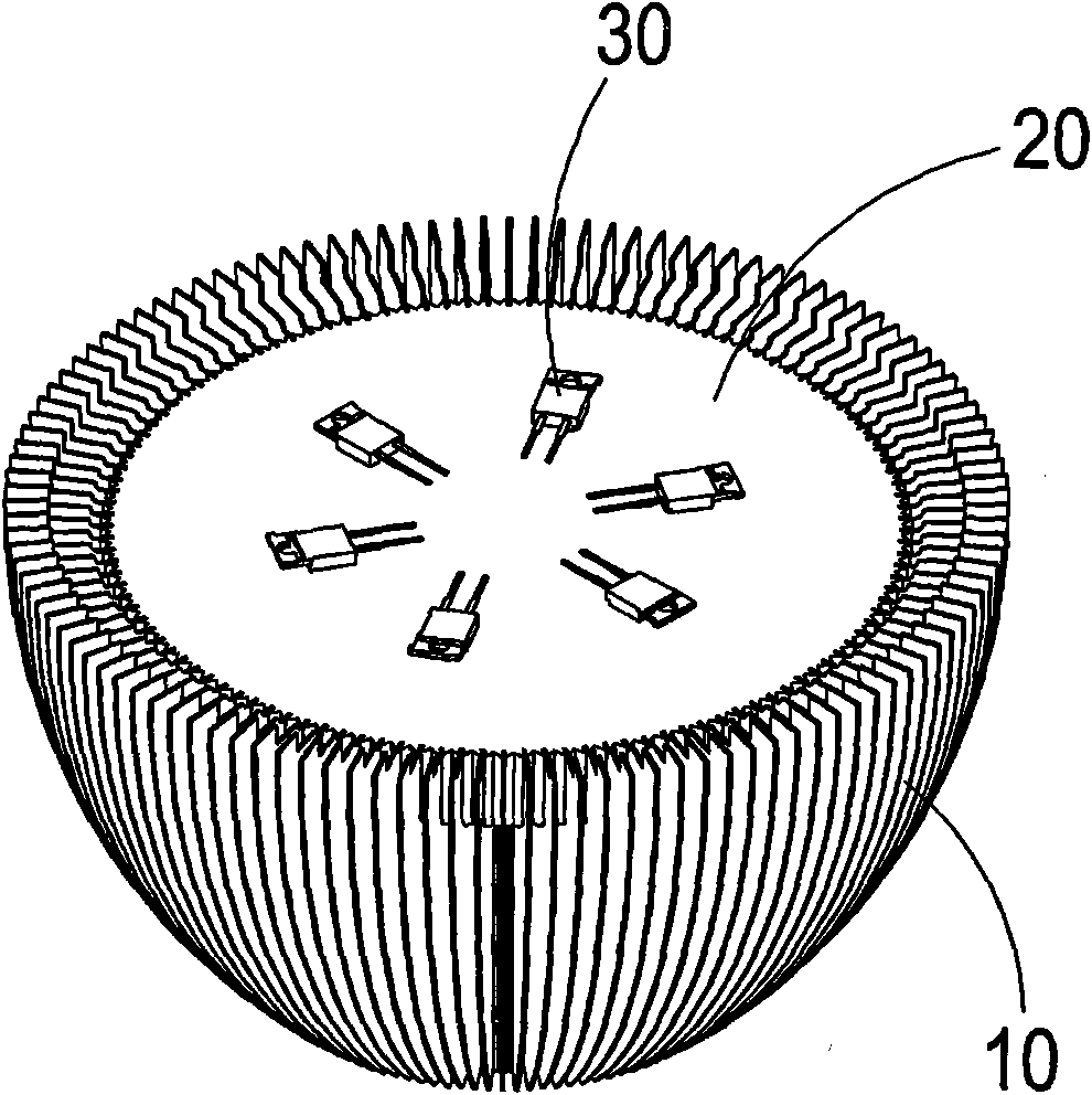
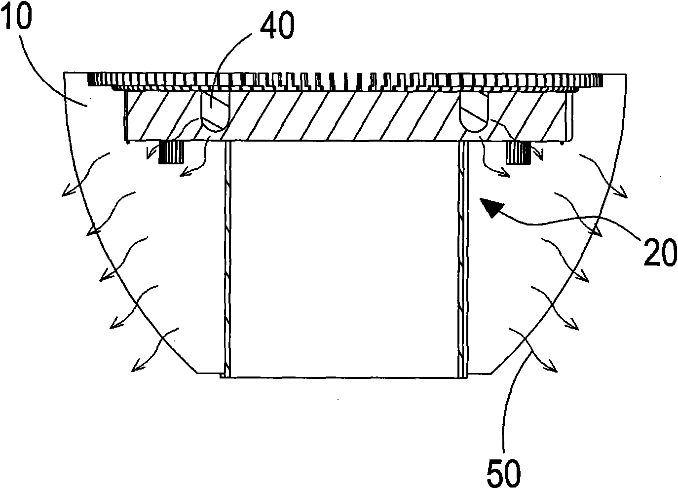
[0025] see figure 1 and figure 2 As shown, it is a perspective view and a perspective exploded view of a preferred embodiment of the present invention. It can be clearly seen from the figure that the present invention includes a heat dissipation fin 10 and an aluminum heat dissipation seat body located on the heat dissipation fin 10. 20 and at least one electronic component 30 which is arranged on the aluminum heat sink body 20 and can be an LED lamp or any heat-generating component, and the aluminum heat sink body 20 is defined with at least one The positions of the electronic components 30 correspond to the copper column heat conductors 40, and the aforementioned copper column heat conductors 40 are set on the aluminum heat dissipation base 20 by using a mold to forcibly close and force it in. It is set on the aluminum heat sink body 20 by...


PUM


Abstract

The invention relates to a radiating structure of electronic assemblies, which comprises a radiating fin, an aluminum radiating base arranged on the radiating fin and at least one electronic assembly arranged on the aluminum radiating base, wherein at least one copper column heat conductor is arranged on the aluminum radiating base via a mold in a forcibly-pressed manner with the position corresponding thereto, so that heat conduction for the electronic assemblies can be realized, thus achieving the advantages of low manufacturing cost, fast production, reduced manufacturing procedures, good environmental friendliness and high radiating efficiency.

Description

technical field [0001] The present invention provides a heat dissipation structure, especially a heat dissipation structure of an electronic component with low manufacturing cost, rapid production, reduced manufacturing process, environmental protection and high heat dissipation efficiency. Background technique [0002] Press, because the light-emitting diode (Light Emitting Diode, LED) uses the principle of directly converting electrical energy into light energy, and applies a voltage to the positive and negative terminals in the semiconductor. When the current passes through, the electrons and holes are combined, and the remaining energy It is released in the form of light, and depending on the material used, the photon energy can be used to generate light of different wavelengths according to its energy level. It is widely used because of its advantages of high brightness, power saving, and long life. In all kinds of technology and daily life, it has become an indispensab...

Claims


Application Information

Patent Timeline
IPC IPC(8): H05K7/20F21V29/00F21Y101/02F21V29/50F21Y115/10
Inventor 黄崇贤
Owner DONG GUAN HAN XU HARDWARE & PLASTIC TECH CO LTD
Why Eureka
Try Eureka