

LED (light emitting diode) ceramic COB (chip on board) light source fluorescent lamp and preparation method thereof
A technology for fluorescent lamps and light sources, applied to circuit substrate materials, printed circuit parts, electrical components, etc., can solve problems such as high cost, poor chemical stability, and large light decay, reduce manufacturing processes and costs, and simplify installation and production and convenience, the effect of light distribution design of lamps and lanterns
- Summary
- Abstract
- Description
- Claims
- Application Information
AI Technical Summary
Problems solved by technology
Method used
Image

Examples
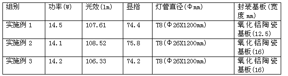
Embodiment 1
[0021] A preparation method of LED ceramic COB light source fluorescent lamp is divided into the following steps:
[0022] The first step: the preparation of the ceramic substrate, select the prepared alumina ceramic plate, and use silver paste to screen the circuit on it. The amount of silver or silver alloy paste in the whole 1.2M lamp tube is 0.9g, and the laser cutting is obtained. The required size of the ceramic substrate, substrate width 12.5mm, that is.
[0023] Among them, the alumina ceramic plate is made by adding alumina with a mass fraction of 5% of silicon oxide, and then adding 35% of alcohol as a flux and 2% of polyphthalamide as a binder. Mix and grind for 24 hours to obtain the desired alumina body, and then sinter at 1550°C for 3 hours.
[0024] The silver paste is made of pure silver by sintering at 750°C for 1 hour.
[0025] The second step: carry out multi-chip integrated COB packaging, select the alumina ceramic substrate prepared in the first step, th...
Embodiment 2
[0029] A preparation method of LED ceramic COB light source fluorescent lamp is divided into the following steps:
[0030] The first step: the preparation of the ceramic substrate, select the prepared alumina ceramic plate, use the silver alloy paste to screen the circuit on it, the amount of the silver alloy paste in the whole 1.2M lamp tube is 1.0g, laser cutting to obtain the required The size of the ceramic substrate, the substrate width is 16mm, that is.
[0031] Among them, the alumina ceramic plate is made by adding alumina with a mass fraction of 5% of silicon oxide, and then adding 35% of alcohol as a flux and 2% of polyphthalamide as a binder. Mix and grind for 24 hours to obtain the desired alumina body, and then sinter at 1600°C for 3 hours.
[0032] The silver alloy paste is prepared by sintering at 800°C for 1 hour with pure silver plus bismuth borosilicate glass with a mass fraction of 9% as a binder.
[0033] All the other are with embodiment 1.
[0034] The...
Embodiment 3
[0036] A preparation method of LED ceramic COB light source fluorescent lamp is divided into the following steps:
[0037] The first step: the preparation of the ceramic substrate, select the prepared alumina ceramic plate, and use the silver alloy paste to screen the circuit on it. The amount of silver or silver alloy paste in the whole 1.2M lamp tube is 1.1g, and the laser cutting is obtained. The required ceramic substrate size, substrate width 16mm, that is.
[0038] Among them, the alumina ceramic plate is made by adding alumina with a mass fraction of 5% of silicon oxide, and then adding 35% of alcohol as a flux and 2% of polyphthalamide as a binder. Mixing and grinding for 24 hours, tape-casting to obtain the desired alumina body, and sintering at 1650°C for 3 hours.
[0039] The silver alloy paste is prepared by sintering at 850°C for 1 hour with pure silver plus bismuth borosilicate glass with a mass fraction of 15% as a binder.
[0040] All the other are with embod...
PUM
 Abstract
Description
Claims
Application Information