A wind channel heat radiator

A heat sink and air duct technology, which is applied in the field of air duct heat sinks, can solve problems such as limited heat dissipation area of ​​aluminum substrates, rising LED chip temperature, and shortened service life, so as to reduce LED light decay, improve luminous efficiency, and prolong The effect of service life

Inactive Publication Date: 2007-11-28
SHANGHAI LONGGUANG SHENJING OPTOELECTRONICS TECH +1
View PDF0 Cites 6 Cited by
  • Summary
  • Abstract
  • Description
  • Claims
  • Application Information

AI Technical Summary

Problems solved by technology

[0002] At present, the problem that restricts the development of high-power LED lighting equipment is the design of its heat dissipation device. The heat dissipation technology used for high-power LED lighting fixtures is to dissipate heat for a limited area of ​​aluminum substrates, and to package high-power LED chips in a small (about 5mm) ) on the copper substrate, make a 1-watt or 3-watt lamp holder, and then fix several (tens to hundreds) 1-watt (3-watt) lamp holders on the aluminum plate with screws or heat-conducting glue for heat dissipation , due to the

Method used


Image

  • A wind channel heat radiator
  • A wind channel heat radiator
  • A wind channel heat radiator

Examples


Example Embodiment

[0017] Example 1

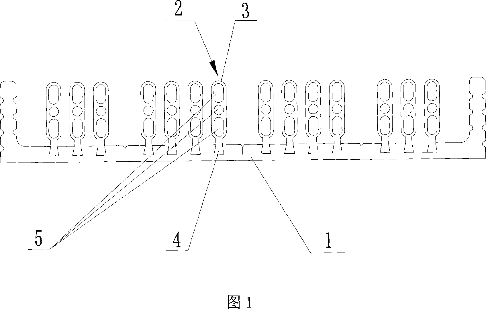
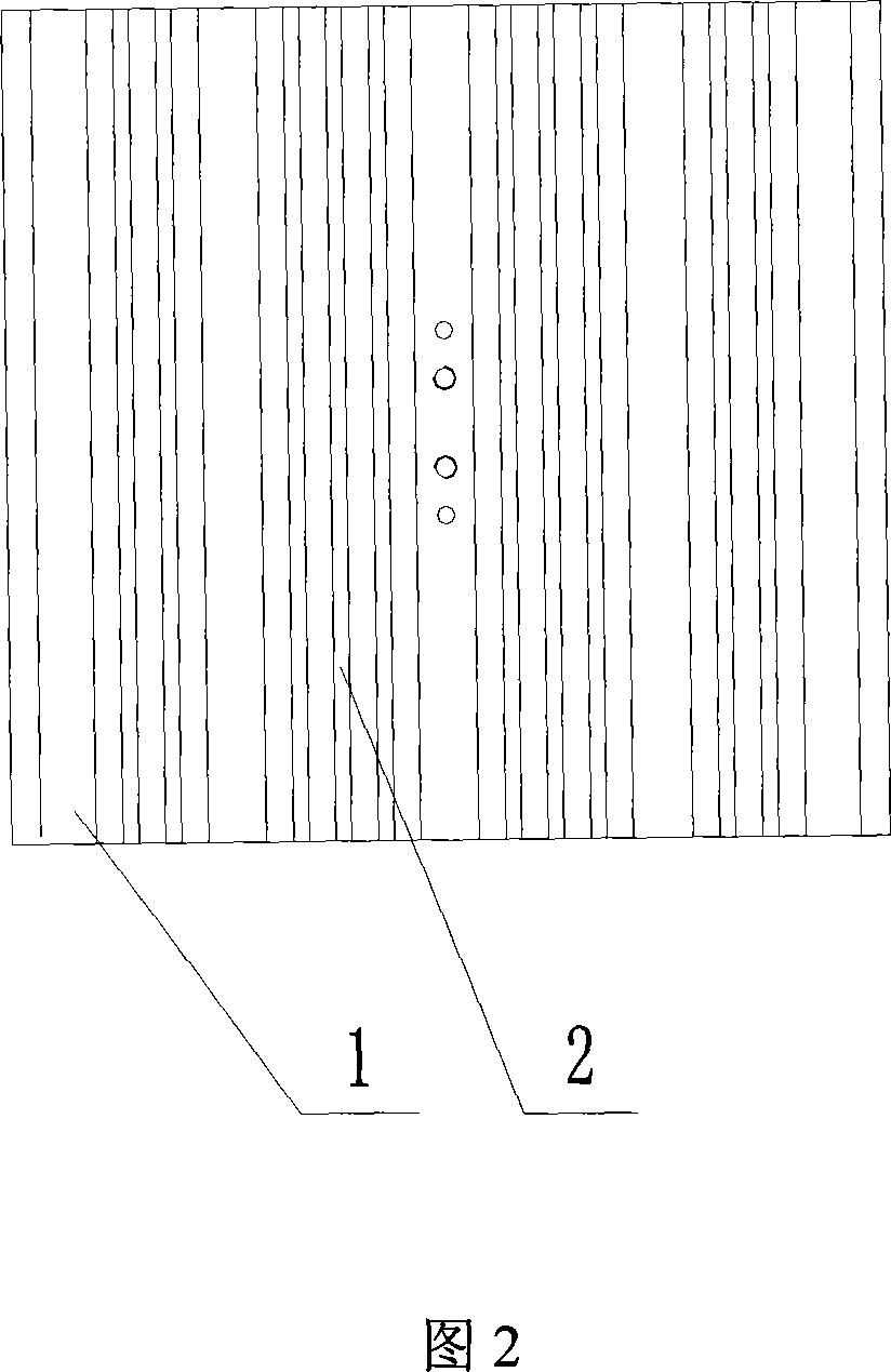
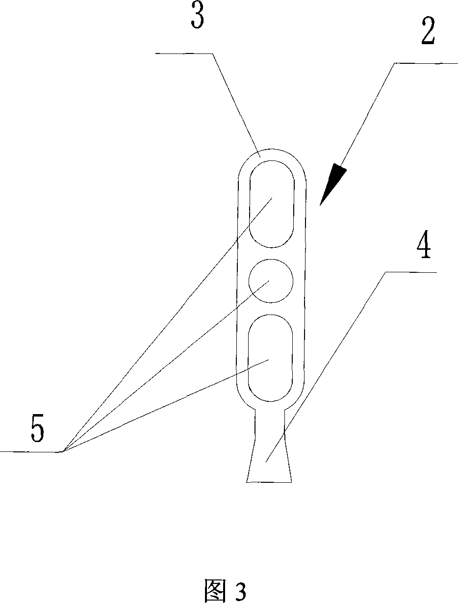
[0018] Several dovetail grooves of the same shape are evenly opened on the heat sink 1 at the same interval. The fin 3 of the air duct type heat sink is provided with three air ducts 5 from top to bottom. The rear ends are inlet and outlet. The air duct radiating fins 4 are integrally arranged at the lower end of the fin body 3. Its shape corresponds to the shape of the dovetail groove on the heat sink 1, and the air duct radiating fin 2 is embedded through it. The strip 4 is vertically embedded on the heat dissipation plate 1 with thermal conductive glue between the two, and also includes a bracket which is movably connected to the two ends of the heat dissipation plate 1 by screws.

Example Embodiment

[0019] Example 2

[0020] Several rectangular grooves of the same shape are evenly opened on the heat sink 1 at the same interval. The fin 3 of the air duct type heat sink on the heat sink 1 is provided with two air ducts 5 from top to bottom. The front and rear ends of the fin body 3 are inlet and outlet, and the shape of the fillet 4 of the air duct type heat sink corresponds to the shape of the rectangular groove on the heat sink 1; the others are the same as the first embodiment.


PUM


Abstract

This invention relates to an air ducted radiator including a radiation plate with several air ducted radiation vanes arranged in definite distance, in which, upper and lower air ducts are set on the radiation vanes to form convection while working and lead out the working heat of the Led effectively, reduce attenuation, increase the luminescent efficiency and prolong the life of the Led.

Description

Technical field [0001] The invention relates to a heat dissipation device, in particular to an air duct type radiator. Background technique [0002] At present, the problem that restricts the development of high-power LED lighting equipment is the design of its heat sink. The current heat dissipation technology used in high-power LED lighting fixtures uses a limited area of ​​aluminum substrate to dissipate heat. The high-power LED chip is packaged in a small (about 5mm) ) On the copper substrate, make a 1 watt or 3 watt lamp cap, and then fix several (tens to hundreds) of 1 watt (3 watt) lamp caps on the aluminum plate with screws or thermal conductive glue for heat dissipation , Due to the thermal resistance between the lamp cap and the aluminum substrate, the heat dissipation area of ​​the aluminum substrate is limited, which makes the Led work heat unable to be discharged, causing the temperature of the Led chip to rise sharply, and the temperature of the aluminum substrate (...

Claims


Application Information

Patent Timeline
IPC IPC(8): H05K7/20H01L23/467F21V29/02F21V29/74F21V29/83
Inventor 谢金崇
Owner SHANGHAI LONGGUANG SHENJING OPTOELECTRONICS TECH
Why Eureka
Try Eureka