Commutator signal conversion control method, device, equipment and storage medium
A technology of signal conversion and control methods, applied to coin-accepting devices, instruments, coin-free or similar appliances, etc., can solve the problems of wasting human and financial resources, large consumption, and high resource maintenance costs, so as to save costs and provide refitting Feasibility, the effect of achieving low-cost maintenance
- Summary
- Abstract
- Description
- Claims
- Application Information
AI Technical Summary
Problems solved by technology
Method used
Image
Examples
Embodiment 1
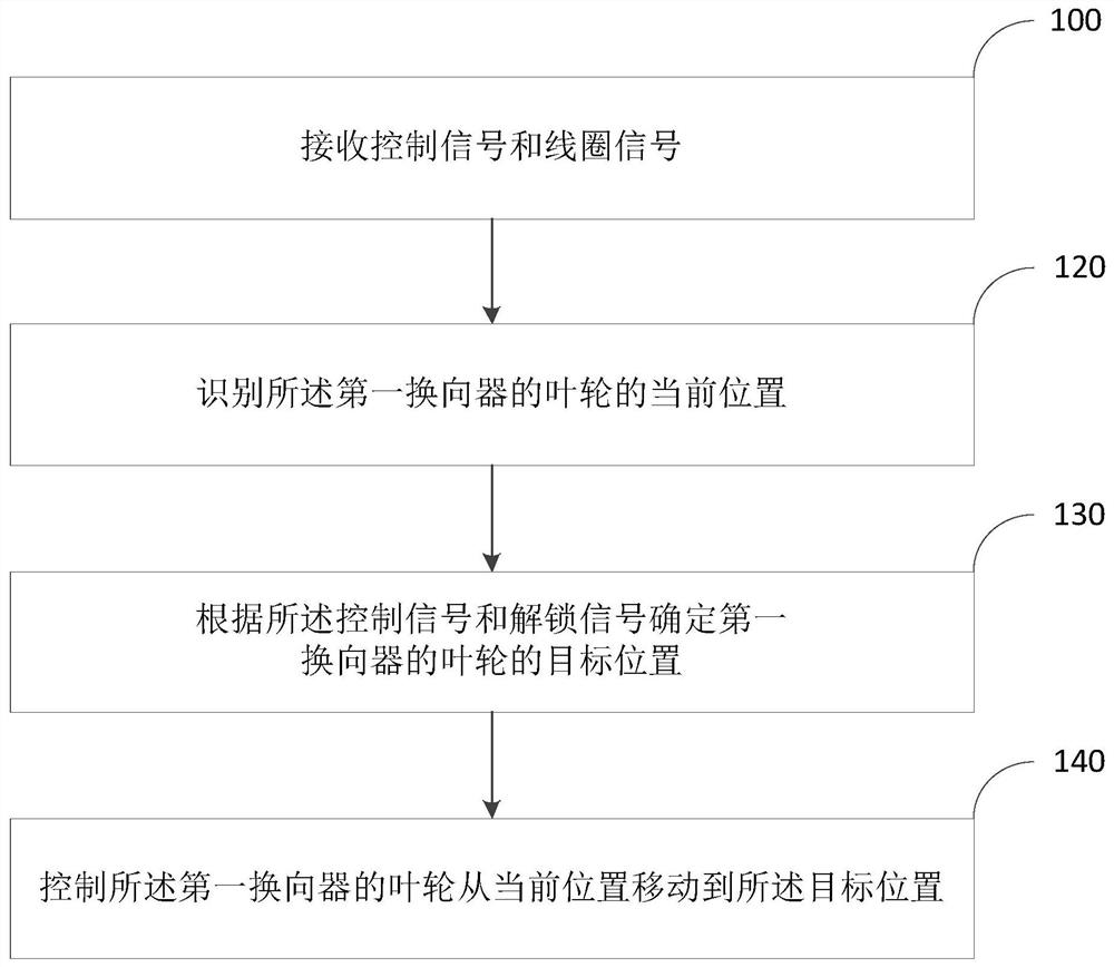
[0041] figure 1 The flow diagram of a commutator signal conversion control method is provided by the embodiment of the present invention, and this embodiment can be applied to the case where the three-phase shifter is replaced with a 360-degree commutator, which includes the following steps:
[0042] Step 100, receive the control signal and the coil signal.
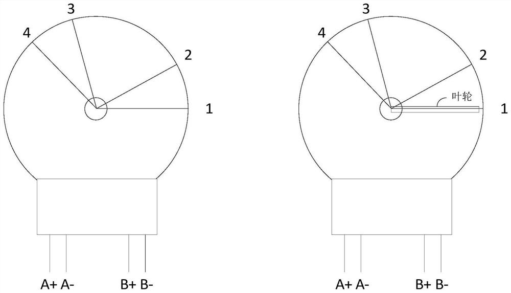
[0043] In this embodiment, the reception control signal and the coil signal are control signals and coil signals for controlling the three-phase exchange, in the present embodiment, the three-phase exchanger is replaced by a 360 degree commutator, but for control The control signal and the coil signal of the three-phase substantifier are constant. See figure 2 In this embodiment, the three-phase converter is a commutating member with two electromagnetic coils, one is called a locking coil, and the other is called a rotating shaft coil. When the lock coil is controlled by a coil signal, the locking coil is in a locked state. ...
Embodiment 2
[0056] This example is a detailed segmentation of the target position of the analysis on the basis of the first example. figure 2 A flow chart of a commutator signal conversion control method according to Embodiment 2 of the present invention, specifically, including:
[0057] Step 200, receive control signals and coil signals.
[0058] Step 210 identify the current position of the impeller of the first commutator.
[0059] Step 220 determines the first target position of the impeller of the first commutator in the same rotating section of the first commutator according to the impeller counterclockwise signal and the impeller clockwise signal.
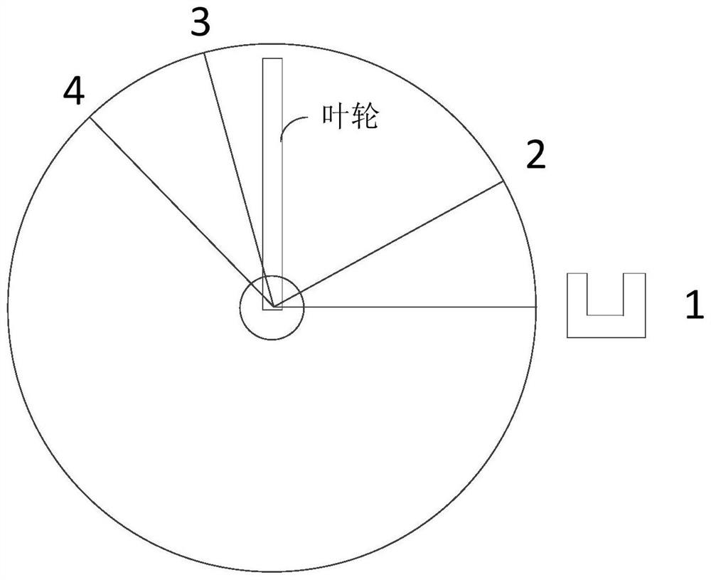
[0060] In this embodiment, first detecting that the B + control line or the B-control line has energization, it means having a control behavior. At this time, there is no need to detect whether the A + control line or the A-control line can control the 360 degree commutator first in the interval. Switch to ensure the real time of the imp...
Embodiment 3
[0069] The present invention provides a commutator signal conversion control method provided by any embodiment of the present invention, and has a functional module and beneficial effects of performing a method according to any embodiment of the present invention. Figure 5 It is a schematic structural diagram of a commutator signal conversion control device 300 in the third embodiment of the present invention. Refer Figure 5 The commutator signal conversion control device 300 provided by the embodiment of the present invention can include:
[0070] The signal detection module 310 is configured to receive a control signal and a coil signal.
[0071] The position analysis module 320 is used to determine the target position of the impeller of the first commutator based on the control signal and the coil signal.
[0072] The position moving module 330 is configured to control the impeller of the first commutator to move from the current position to the target position.
[0073] Furthe...
PUM
 Abstract
Description
Claims
Application Information
 - R&D
- Intellectual Property
- Life Sciences
- Materials
- Tech Scout
- Unparalleled Data Quality
- Higher Quality Content
- 60% Fewer Hallucinations
Browse by: Latest US Patents, China's latest patents, Technical Efficacy Thesaurus, Application Domain, Technology Topic, Popular Technical Reports.
© 2025 PatSnap. All rights reserved.Legal|Privacy policy|Modern Slavery Act Transparency Statement|Sitemap|About US| Contact US: help@patsnap.com


