One-key automatic unlocking device

An automatic unlocking and moving handle technology, applied in the server field, can solve problems such as being unable to pop open and unlock by itself, and achieve the effects of simple structure, guaranteed stability, and convenient operation

Active Publication Date: 2020-03-06
SUZHOU LANGCHAO INTELLIGENT TECH CO LTD
View PDF10 Cites 0 Cited by
  • Summary
  • Abstract
  • Description
  • Claims
  • Application Information

AI Technical Summary

Problems solved by technology

However, some previous solutions may appear in the unlocking process in some narrow and compact scenarios. The unlocking device cannot be opened and unlocked by itself due to gravity or friction.

Method used


Image

  • One-key automatic unlocking device
  • One-key automatic unlocking device
  • One-key automatic unlocking device

Examples


Embodiment Construction

[0028] The one-button automatic unlocking device of the present invention will be described in detail below with reference to the accompanying drawings.

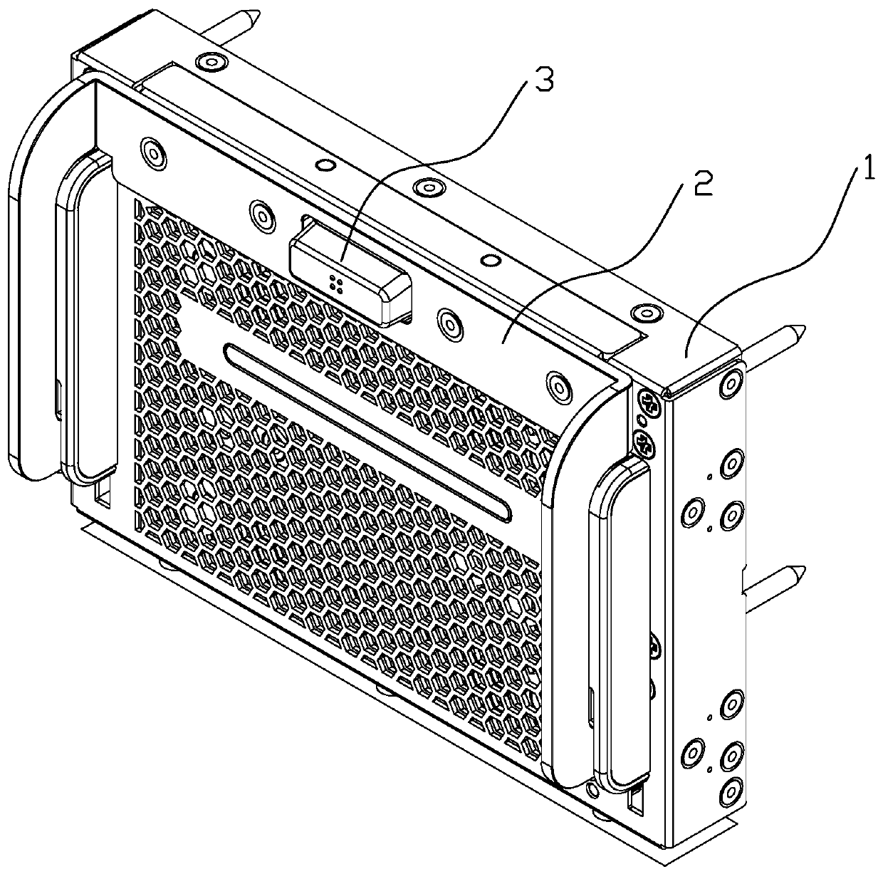
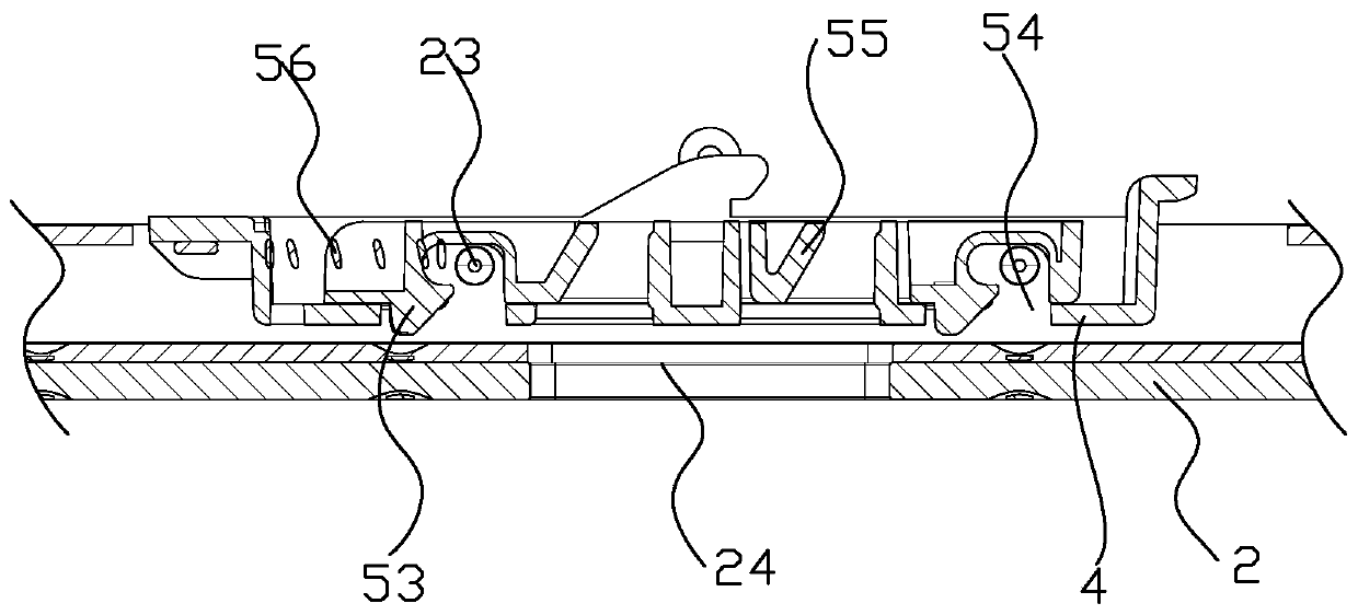
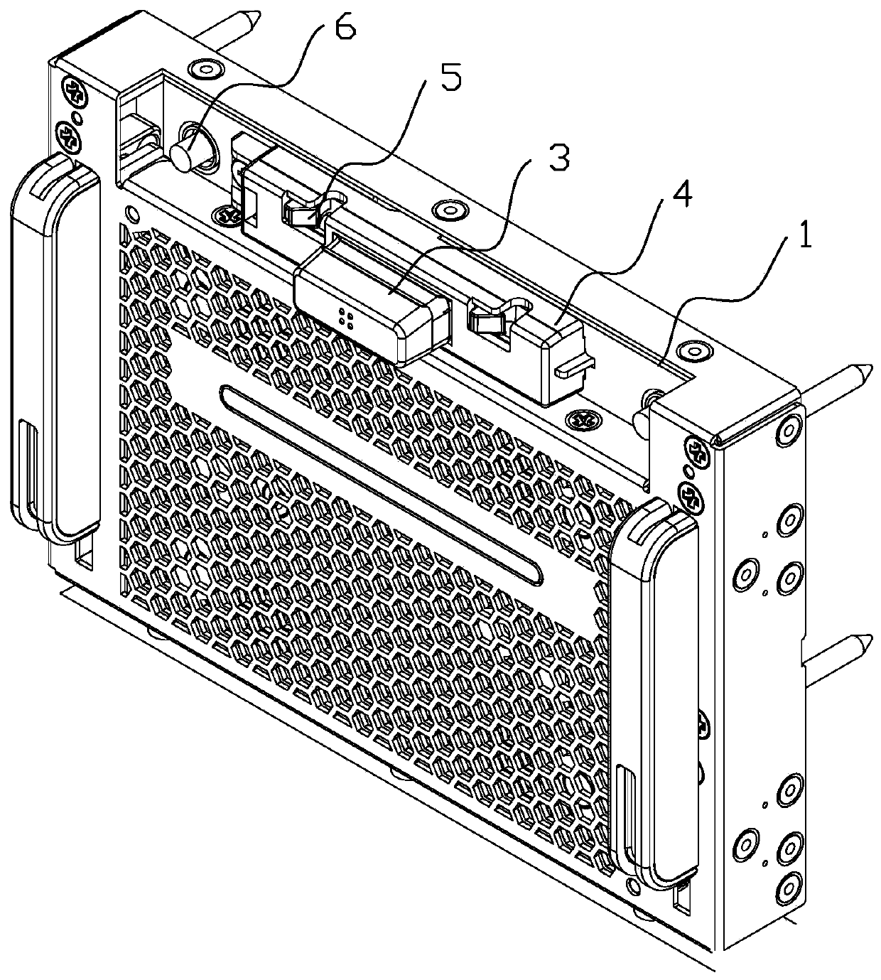
[0029] like Figure 1 to Figure 8 As shown, the one-button automatic unlocking device of the present invention has a structure including a frame 1 and a connecting rod booster assembly 2, and the two ends of the opening of the connecting rod booster assembly 2 are respectively hinged with the frame 1 through pin shafts, and also includes a pressing part 3. The button base 4 and the locking part 5, one end of the locking part 5 is fastened with the button base 4 through a compression spring 56, the locking part 5 is connected with the frame 1 through screws, and the movement of the pressing part 3 The handle 32 passes through the connecting rod booster assembly 2, the button base 4, the locking part 5 and the limit card slot 11 on the frame 1 in sequence. The function of the limit card slot is to cooperate with the hook at th...


PUM


Abstract

The invention discloses a one-key automatic unlocking device. The device comprises a rack and a connecting rod assisting assembly. The two ends of an opening of the connecting rod assisting assembly are hinged to the rack through pin shafts correspondingly. The device further comprises a pressing component, a button base and a locking component. One end of the locking component is matched and buckled with the button base through a compression spring. The locking component is connected with the rack through a screw. A moving handle of the pressing component sequentially penetrates through the connecting rod power assisting assembly, the button base, the locking component and a limiting clamping groove in the rack. The front-back movement of a movable handle controls the left-right movementof the locking part, so opening or closing of the connecting rod assisting assembly is achieved. According to the unlocking device, certain pressure is applied to the button, transverse movement of the locking block is controlled while the button moves forwards, opening and one-key automatic unlocking of the connecting rod assisting assembly are achieved, and the unlocking device is simple in structure and convenient to operate.

Description

technical field [0001] The invention relates to the field of servers, in particular to a one-key automatic unlocking device. Background technique [0002] The existing unlocking devices in the field of servers are generally composed of two or three structural parts, which mainly use the principle of leverage to save labor, and use the principles of rotation and deformation of the active arm to unlock. However, some previous solutions may appear in the unlocking process in some narrow and compact scenarios, and the unlocking device cannot be opened and unlocked by itself due to gravity or friction. At that time, the unlocking device can only be pulled out with other tools to unlock the entire module or node. Contents of the invention [0003] The purpose of the present invention is to provide a one-button automatic unlocking device, which has a reasonable structure and is easy to operate. During the whole unlocking process, one-button unlocking can be realized only by pres...

Claims


Application Information

Patent Timeline
IPC IPC(8): H05K7/14
CPCH05K7/1487H05K7/1489
Inventor 余世茂尹秀忠张海龙
Owner SUZHOU LANGCHAO INTELLIGENT TECH CO LTD
Why Eureka
Try Eureka