Rotation type valve

A rotary and rotary valve technology, applied in the direction of sliding valves, valve devices, engine components, etc., can solve the problems of people or objects collision, large space, damage, etc., to avoid collisions, ensure safety, and reduce damage.

Inactive Publication Date: 2017-01-25
DEYANG DIXINJIA VALVE MFR
View PDF1 Cites 12 Cited by
  • Summary
  • Abstract
  • Description
  • Claims
  • Application Information

AI Technical Summary

Problems solved by technology

However, most of the components that control the valve are exposed at the outer end, o

Method used


Image

  • Rotation type valve
  • Rotation type valve
  • Rotation type valve

Examples


Embodiment 1

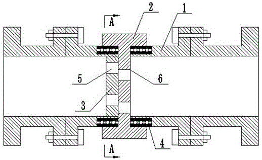
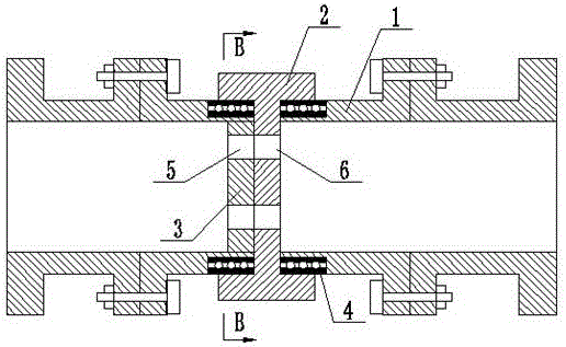
[0025] Such as Figure 1 to Figure 4 As shown, a rotary valve includes a pipeline 1, a rotary valve plate 2 and a fixed valve plate 3, the inner wall of the end of the pipeline 1 is connected with a fixed valve plate 3, and the fixed valve plate 3 is provided with a fixed orifice 5. The fixed orifice 5 is offset from the central axis position of the fixed valve plate 3, and the outer end of the pipe 1 is fitted with an annular bearing 4, and the rotating valve plate 2 is installed on the annular bearing 4, and the rotating The valve plate 2 is provided with a rotating orifice 6 which is coaxial with the fixed orifice 5 and has the same diameter.

[0026] In practical application, the rotating valve plate 2 rotates relative to the fixed valve plate 3, so that the rotating orifice 6 and the fixed orifice 5 overlap or intersect to realize the closing and opening of the liquid in the valve. Most of the control components of this valve are set It is installed inside the valve, occ...

Embodiment 2

[0028] Such as Figure 1 to Figure 4 As shown, a rotary valve includes a pipeline 1, a rotary valve plate 2 and a fixed valve plate 3, the inner wall of the end of the pipeline 1 is connected with a fixed valve plate 3, and the fixed valve plate 3 is provided with a fixed orifice 5. The fixed orifice 5 is offset from the central axis position of the fixed valve plate 3, and the outer end of the pipe 1 is fitted with an annular bearing 4, and the rotating valve plate 2 is installed on the annular bearing 4, and the rotating The valve plate 2 is provided with a rotating orifice 6 which is coaxial with the fixed orifice 5 and has the same diameter.

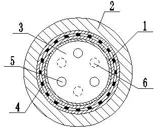
[0029] The number of fixed orifices 5 is 3-5, and the number of rotating orifices 6 is the same as that of fixed orifices 5 .

[0030] The annular bearing 4 is made of nitrile rubber.

[0031] In practical application, the rotating valve plate 2 rotates relative to the fixed valve plate 3, so that the rotating orifice 6 and the fix...

Embodiment 3

[0035] Such as Figure 1 to Figure 4 As shown, a rotary valve includes a pipeline 1, a rotary valve plate 2 and a fixed valve plate 3, the inner wall of the end of the pipeline 1 is connected with a fixed valve plate 3, and the fixed valve plate 3 is provided with a fixed orifice 5. The fixed orifice 5 is offset from the central axis position of the fixed valve plate 3, and the outer end of the pipe 1 is fitted with an annular bearing 4, and the rotating valve plate 2 is installed on the annular bearing 4, and the rotating The valve plate 2 is provided with a rotating orifice 6 which is coaxial with the fixed orifice 5 and has the same diameter.

[0036] The number of fixed orifices 5 is 3-5, and the number of rotating orifices 6 is the same as that of fixed orifices 5 .

[0037] The annular bearing 4 is made of nitrile rubber.

[0038] The fixed valve plate 3 is threadedly connected with the pipeline 1 .

[0039] The rotary valve plate 2 is provided with a scale.

[0040]...


PUM


Abstract

The invention relates to a rotation type valve which comprises a pipeline, a rotary valve plate and a fixed valve plate. The fixed valve plate is connected with the inner wall of a pipeline end head, fixed flow holes are formed in the fixed valve plate, and deflect from the central axis of the fixed valve plate; an annular bearing sleeves is arranged on the outer end of the pipeline end head in a sleeving mode, the rotary valve plat is arranged on the annular bearing; rotary flow holes are formed in the rotary valve plate, the rotary flow holes and the fixed flow holes are coaxially arranged, and the apertures of the rotary flow holes are the same as that of the fixed flow holes. Through the rotation of the rotary valve plate relative to the fixed valve plate, the rotary flow holes and the fixed flow holes coincide or intersect, thus the fluid in the valve opens and closes. Most control parts of the valve are arranged inside of the valve, the occupied exterior space of the valve is small, the problem of collision of people or items during the operation is avoided, thus the safety is ensured, unnecessary injuries are reduced. The rotation type valve is simple in structure and convenient to operate.

Description

technical field [0001] The invention relates to the field of valve connection structures, in particular to a rotary valve. Background technique [0002] A valve is a device used to control the direction, pressure, and flow of a fluid in a fluid system. It is a device that makes the medium (liquid, gas, powder) in the piping and equipment flow or stops and can control its flow. The control of the valve can be used A variety of transmission methods, such as manual, electric, hydraulic, pneumatic, turbine, electromagnetic, electromagnetic hydraulic, electrohydraulic, pneumatic hydraulic, spur gear, bevel gear drive, etc., for simple opening or closing, the valve depends on the drive Or the automatic mechanism makes the opening and closing parts move up and down, slide, swing or turn, so as to change the size of the flow channel area to realize its control function. [0003] The patent number is CN105465470A, and the application date is 2015-12-31, which discloses a valve, incl...

Claims


Application Information

Patent Timeline
IPC IPC(8): F16K3/08F16K3/312F16K3/314F16K37/00
CPCF16K3/08F16K3/312F16K3/314F16K37/0016
Inventor 黄斌刘波唐明元
Owner DEYANG DIXINJIA VALVE MFR
Why Eureka
Try Eureka