
High-speed railway platform door based on dislocation structure and control method thereof

A platform door, high-speed rail technology, applied in the direction of stations, windows/doors, building components, etc., can solve the problem of inability to open the door in alignment, and inability to adjust the position of the door for different models.

Inactive Publication Date: 2020-11-24
CHENGDU TANGYUAN ELECTRICAL APPLIANCE
View PDF7 Cites 11 Cited by
  • Summary
  • Abstract
  • Description
  • Claims
  • Application Information

AI Technical Summary

Problems solved by technology

However, in this technical solution, since the left / right sliding stroke is fixed, and each sliding door only realizes the door opening action through one-way movement, the adaptability of this method to vehicle models is actually limited, and it cannot be adjusted according to different models. Adjust the door opening position. For example, when the train door is just in the overlapping area of ​​the left / right sliding door, this solution cannot realize the alignment door opening

Method used


Image

  • High-speed railway platform door based on dislocation structure and control method thereof
  • High-speed railway platform door based on dislocation structure and control method thereof
  • High-speed railway platform door based on dislocation structure and control method thereof

Examples


Embodiment 1

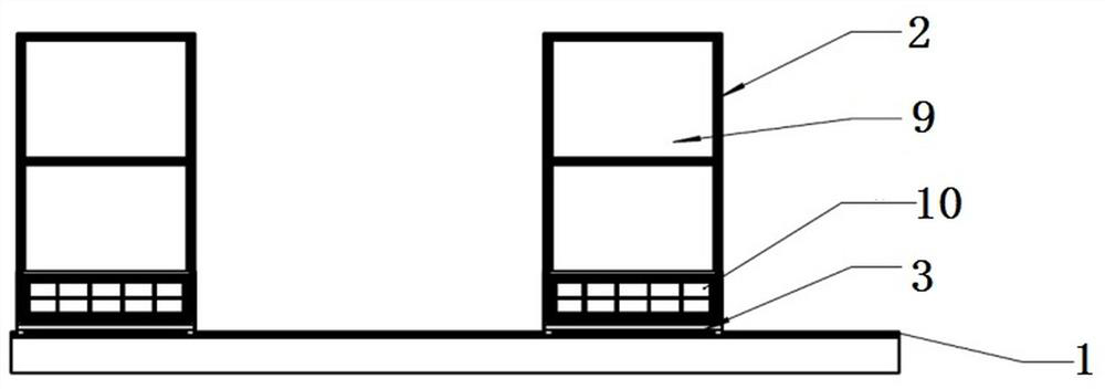
[0037] This embodiment discloses a high-speed rail platform door based on a dislocation structure, such as figure 1 , including two rows of front and rear sliding door groups parallel to each other arranged along the length direction of the edge of the platform, each row of sliding door groups includes a number of movable unit doors 2 set upright, and each movable unit door 2 is provided with an independent The drive unit 5 is driven by the drive unit 5 and independently slides left and right along the length direction of the edge of the platform; the movable unit doors 2 in the front and rear rows of sliding door groups are all set at intervals, and the adjacent two movable units The distance between the doors 2 is less than or equal to the width of the single movable unit door 2, so that it can be ensured that the movable unit doors 2 on the two rows of sliding door groups can at least form an end-to-end connection with no gap in the middle when they are misplaced. The parti...

Embodiment 2

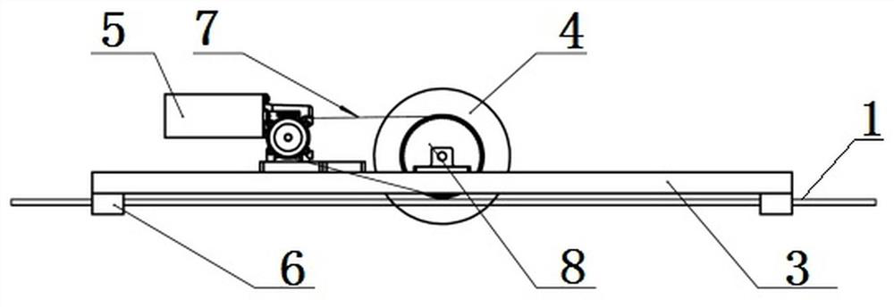
[0041] On the basis of the technical solution of the above-mentioned embodiment 1, further, each movable unit door 2 includes a door body and a bearing plate 3 arranged at the bottom of the door body, such as image 3 and 4 , the bottom of the bearing plate 3 is provided with a motion wheel 4 for sliding on the ground or rail surface; the bearing is also provided with a servo motor with a reducer and provides power for the motion wheel 4 through a synchronous belt 7; the motion The wheel 4 is provided with a synchronous gear 8, the servo motor drives the driving gear through a reducer, and the driving gear transmits power to the synchronous gear 8 on the sports wheel 4 through the synchronous belt 7, and the synchronous gear 8 drives the sports wheel 4 to rotate. The carrying plate 3 is a flat mounting plate arranged horizontally and an opening for installing the moving wheel 4 is opened in the middle, and the moving wheel 4 is arranged at the opening through a mounting bearin...

Embodiment 3

[0052] Corresponding to the technical solutions of the above-mentioned embodiments 1 and 2, this embodiment also provides the above-mentioned control method of the high-speed railway platform door based on the dislocation structure, including the door closing step and the door opening step;

[0053] The closed-door steps, such as Figure 5 and 6 , when the train does not enter the station to stop and unload passengers and after the train leaves the station, control each movable door unit on the front and rear rows of sliding door groups to move to the stop position along the direction of the slide rail 1 under the drive of the drive unit 5, and all activities When the unit door 2 moves to the stop position, the movable door units on each row of sliding door groups are arranged at intervals, and the distance between two adjacent movable unit doors 2 is not greater than the width of a single movable unit door 2, The two movable unit doors 2 adjacent to each other on the front a...


PUM


Abstract

The invention belongs to the field of platform screen doors of high-speed railways / intercity railways and discloses a high-speed railway platform door based on a dislocation structure and a control method thereof. The high-speed railway platform door comprises at least two slide rails which are parallel to each other and are arranged in the length direction of the platform edge, and a plurality ofmovable unit doors which are provided with driving units and are capable of sliding along the respective slide rails are arranged on the slide rails; and each movable unit door comprises a bearing plate at the bottom and a door body unit vertically arranged on the bearing plate, a moving wheel and guide sliding blocks are arranged on the bearing plate, the bearing plate is arranged in each sliding rail through the guide sliding blocks in a sliding mode, the moving wheel is driven via each driving unit to drive the whole movable unit door to move on the ground of the platform in the directionof the sliding rails. The high-speed railway platform door is based on the dislocation structure, a plurality of movable unit doors are arranged on a plurality of rows of slide rails in a staggered manner, and the door opening position is adjusted in real time according to the specification of the incoming vehicle type so as to adapt to various vehicle types on the high-speed railway platform.

Description

technical field [0001] The invention belongs to the field of high-speed railway / intercity railway platform screen doors, in particular to a high-speed railway platform door based on a dislocation structure. Background technique [0002] The platform screen door system is set on the edge of the platform to isolate the passenger waiting area from the train operation area, and corresponds to the train door. It can control the opening and closing of sliding doors in multiple levels. Generally, there are full-height, half-height, airtight and Non-airtight, referred to as screen door or platform door. When the train arrives and departs, the screen door can be opened and closed automatically, and the driving space is mechanically isolated from the passenger waiting space, creating a safe and comfortable waiting environment for passengers. [0003] In the operating environment of high-speed railways and intercity railways, due to the high traffic density, factors such as high-speed...

Claims


Application Information

Patent Timeline
IPC IPC(8): E06B3/46E05F15/643E05D13/00B61B1/02
CPCE06B3/4636E05D13/00E05F15/643B61B1/02
Inventor 占栋张志豪苏轩曹伟唐清谢明生肖建明黄华清李丰李文刚朱强王明慧严余松张学鹏景博
Owner CHENGDU TANGYUAN ELECTRICAL APPLIANCE
Learn More