Compound broadband muffler with multi-layer structure

A multi-layer structure, muffler technology, applied in the direction of intake muffler, machine/engine, engine components, etc., can solve the problems of complicated filter processing technology and high price, and achieve the effect of avoiding use, eliminating noise, and improving noise reduction.

Pending Publication Date: 2020-03-10
MANNHUMMEL FILTER SHANGHAI
View PDF1 Cites 4 Cited by
  • Summary
  • Abstract
  • Description
  • Claims
  • Application Information

AI Technical Summary

Problems solved by technology

This impedance composite design needs to add a filter screen to block the sound-absorbing cotton inside the muffler. The processing technology of the filter screen is complicated and the price is high.

Method used


Image

  • Compound broadband muffler with multi-layer structure
  • Compound broadband muffler with multi-layer structure
  • Compound broadband muffler with multi-layer structure

Examples


Embodiment 1

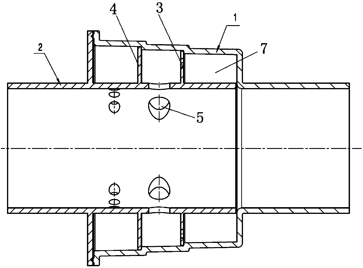
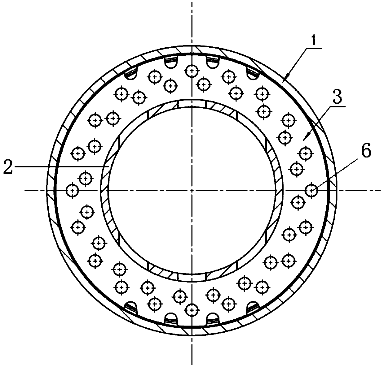
[0024] A composite broadband muffler with a multi-layer structure, such as figure 1 As shown, it includes a shell 1 and a central tube 2 coaxially arranged in the shell. A closed sound-absorbing chamber is formed between the central pipe 2 and the shell 1. Two partitions 3 and 4 are arranged in the sound-absorbing chamber, and the central pipe 2 is provided with The sound-absorbing hole 5 that communicates with independent space. In this embodiment, the shell 1 is a stepped cylindrical structure, and the partitions are arranged at the subsections of the stepped cylindrical shell 1. The ratio of the diameter of the shell 1 to the diameter of the central tube is about 1.5:1, and the partition is a circle. The ring is vertically arranged on the central tube, and the central tube and the shell are welded together. The partitions 3 and 4 divide the sound-absorbing cavity into three independent spaces 7 . Wherein, the leftmost independent space 7 communicates with the central pipe...

Embodiment 2

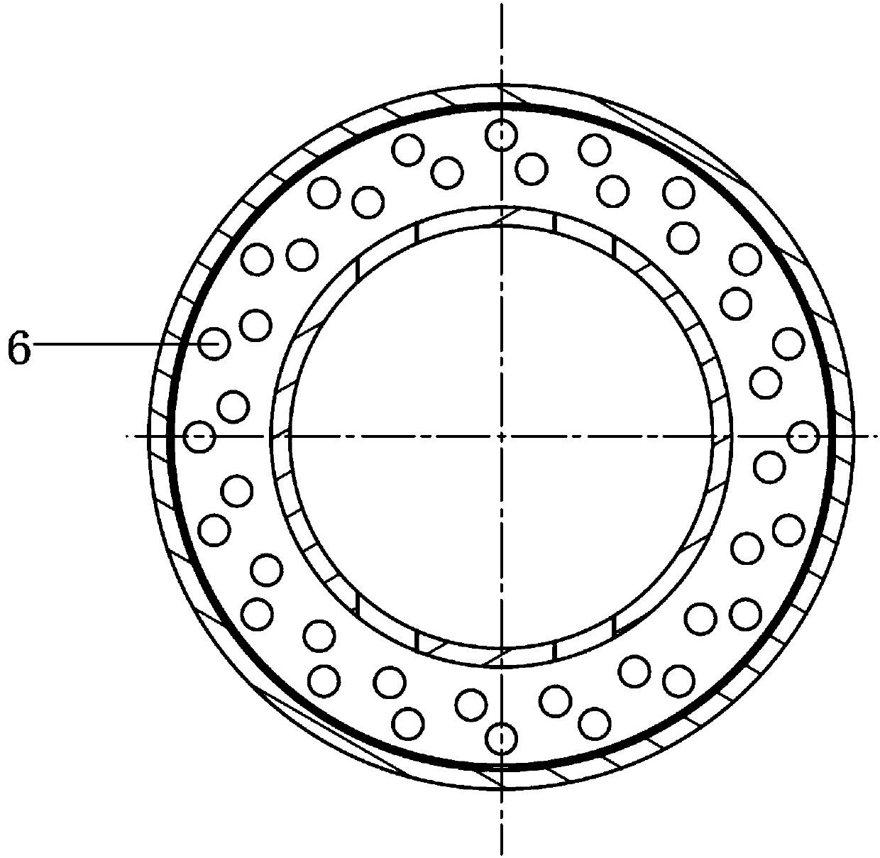
[0027] The difference from Example 1 is that only one partition 3 is provided in this embodiment. The partition 3 divides the airtight silencer cavity formed between the central tube 2 and the shell 1 into two independent spaces. The left independent space and the central tube 2 pass through the silencer. The hole 5 is connected, and the air hole 6 is provided on the partition 3, so that the independent space 7 on the right is connected with the one on the left.

Embodiment 3

[0029] Different from Embodiment 1, this embodiment only has three partitions. The partitions divide the airtight silencer cavity formed between the central tube 2 and the shell 1 into 4 independent spaces. From left to right, the first independent space And the third independent space is communicated with the center pipe 2 through the sound-absorbing hole 5, and the partition plate 3 between the second and fourth independent space and the adjacent independent space that is not communicated with the center pipe 2 through the sound-absorbing hole 5 is provided with a through-hole There are 6 air holes, and the other partitions do not have holes, so that a multi-layer composite porous resonant cavity can be formed. By using the impedance of the multi-layer resonant structure to cause the reflection of sound waves to eliminate noise, it has a better noise reduction effect and can eliminate wider frequency noise.


PUM


Abstract

The invention relates to a compound broadband muffler with a multi-layer structure. The compound broadband muffler comprises a shell and a central pipe coaxially arranged in the shell, a closed muffling cavity is formed between the central pipe and the shell, one or more partition plates which divide the muffling cavity into two or more independent spaces are arranged in the muffling cavity, a plurality of muffling holes which communicate with the independent spaces are formed in the central pipe, and air holes are formed in the partition plates between the independent spaces which not communicate with the central pipe through the muffling holes and the adjacent independent spaces. Compared with the prior art, according to the compound broadband muffler, holes are formed in the partition plates, a multi-layer compound porous resonant cavity is formed, and a compound resonant cavity with a plurality of cavities in the structure is formed; and the impedance of the multi-layer resonant structure is utilized to generate the reflection of sound wave for muffling, from the acoustic point of view, the compound broadband muffler is composed of a porous tube resonant cavity and the multi-layer compound porous resonant cavity, the better muffling effect is achieved, and the noise with a wider frequency can be eliminated.

Description

technical field [0001] The invention relates to a muffler, in particular to a composite broadband muffler with a multi-layer structure. Background technique [0002] At present, the broadband muffler of the automobile air intake system mostly adopts the impedance composite design or the single porous noise reduction design. For example, Chinese patent CN205977488U discloses a muffler, an air intake system and a vehicle. The muffler includes: an air intake pipe, on which a muffler hole is provided; , the partition device is arranged between the air intake pipe and the housing and separates the space between the air intake pipe and the housing to form a plurality of sound-absorbing chambers with different volumes, and the sound-absorbing chambers are different from the sound-absorbing chambers. The holes are connected. The single porous noise reduction design has a narrow noise reduction frequency band and a single performance. The impedance compound muffler has a wide nois...

Claims


Application Information

Patent Timeline
Patent Type & Authority Applications(China)
IPC IPC(8): F02M35/12
CPCF02M35/1216F02M35/1266
Inventor 王智易曹晨吉
Owner MANNHUMMEL FILTER SHANGHAI
Why Eureka
Try Eureka