Laser radar system based on MEMS scanning mirror

A laser radar and scanning mirror technology, applied in radio wave measurement systems, instruments, etc., can solve the problems of low detection accuracy and resolution, low utilization of laser beam light energy, and short detection distance.

Pending Publication Date: 2020-03-10
TANWAY TECH (BEIJING) CO LTD
View PDF7 Cites 6 Cited by
  • Summary
  • Abstract
  • Description
  • Claims
  • Application Information

AI Technical Summary

Problems solved by technology

However, in related technologies, the light energy utilization rate of the laser beam emitted by the ...

Method used


Image

  • Laser radar system based on MEMS scanning mirror
  • Laser radar system based on MEMS scanning mirror
  • Laser radar system based on MEMS scanning mirror

Examples


Embodiment Construction

[0035] Various exemplary embodiments, features, and aspects of the present disclosure will be described in detail below with reference to the accompanying drawings. The same reference numbers in the figures indicate functionally identical or similar elements. While various aspects of the embodiments are shown in drawings, the drawings are not necessarily drawn to scale unless specifically indicated.

[0036] The word "exemplary" is used exclusively herein to mean "serving as an example, embodiment, or illustration." Any embodiment described herein as "exemplary" is not necessarily to be construed as superior or better than other embodiments.

[0037] In addition, in order to better illustrate the present disclosure, numerous specific details are given in the following specific implementation manners. It will be understood by those skilled in the art that the present disclosure may be practiced without some of the specific details. In some instances, methods, means, componen...


PUM

PropertyMeasurementUnit
Diameteraaaaaaaaaa

Abstract

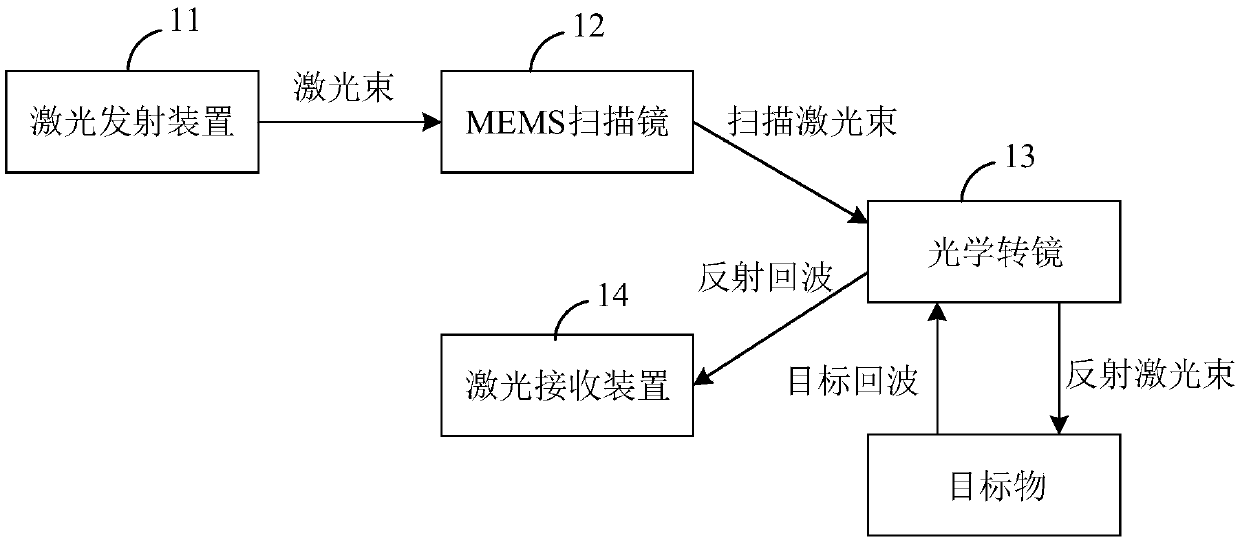
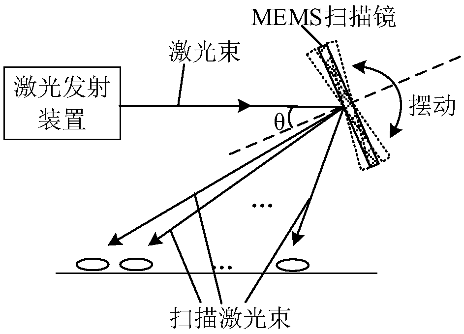
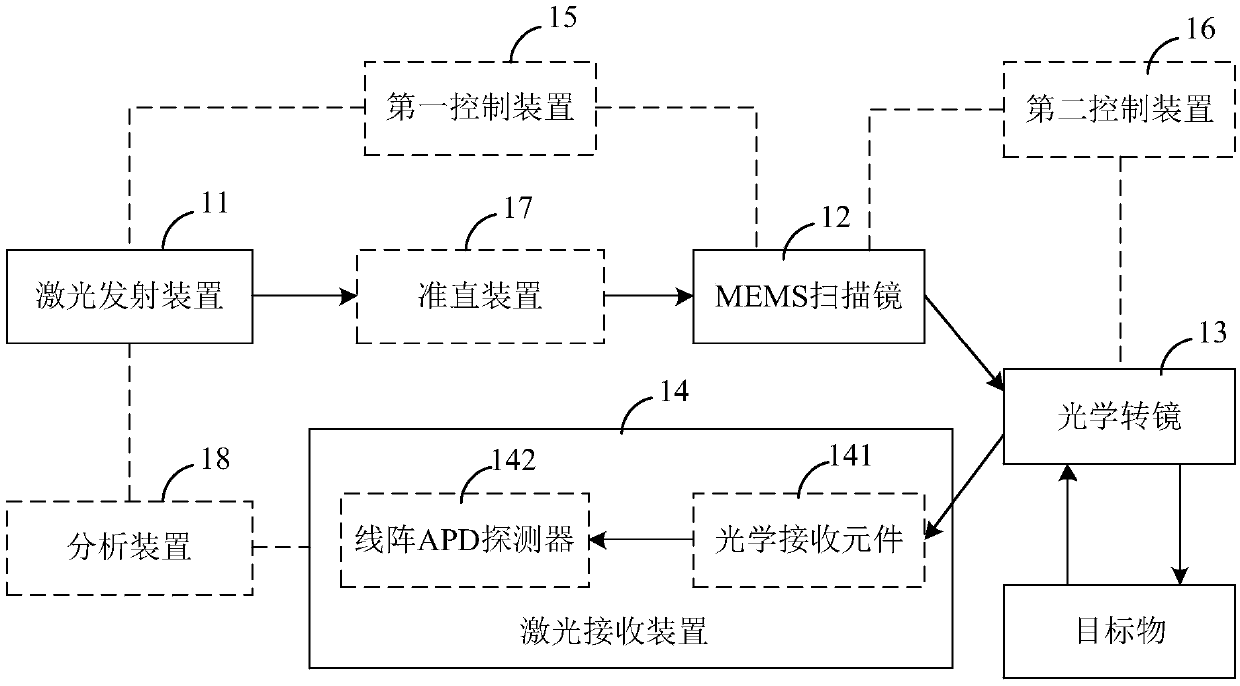
The invention relates to a laser radar system based on an MEMS scanning mirror. The system comprises: a laser emitting device used for emitting a laser beam; the MEMS scanning mirror that is used forreflecting the laser beam to form a scanning laser beam, the MEMS scanning mirror can swing within a preset deflection angle range to realize beam scanning in a first direction, and the emitting direction of the scanning laser beam is related to the deflection angle of the MEMS scanning mirror; an optical rotating mirror that is used for reflecting the scanning laser beam to form a reflection laser beam, and the optical rotating mirror rotates or swings around a rotating shaft of the optical rotating mirror to realize beam scanning in a second direction; the optical rotating mirror is also used for reflecting the received target echo to form a reflection echo, and the target echo is an echo after the reflection laser beam is subjected to diffuse reflection on a target object; a laser receiving device is used for receiving the reflection echoes. According to the system, the light energy utilization rate of the laser beams is high, the detection distance of the system is large, and the detection precision and the detection resolution are high.

Description

technical field [0001] The present disclosure relates to the technical field of laser radar, in particular to a laser radar system based on a MEMS scanning mirror. Background technique [0002] Lidar technology is a radar system that emits laser beams to detect the position, speed and other characteristic quantities of the target. The lidar technology calculates the feature quantity of the target based on the Time of Flight (TOF) method. Lidar technology is widely used in autonomous driving, surface topography mapping, military reconnaissance, atmospheric detection, robot vision and other fields. However, in related technologies, the light energy utilization rate of the laser beam emitted by the lidar is low, the detection distance is short, and the detection accuracy and detection resolution are low. Contents of the invention [0003] In view of this, the present disclosure proposes a laser radar system based on a MEMS scanning mirror. [0004] According to an aspect o...

Claims


Application Information

Patent Timeline
IPC IPC(8): G01S7/481
CPCG01S7/481G01S7/4817
Inventor 王世玮孟玉凰郑睿童沈罗丰
Owner TANWAY TECH (BEIJING) CO LTD
Why Eureka
Try Eureka