Radar microsensor for detection, tracking, and classification

a microsensor and tracking technology, applied in the field ofradar microsensors for detection, tracking, and classification, can solve the problems of reducing affecting the detection accuracy of the system, so as to and improve the performance of the fmcw detection, tracking and classification algorithm. , the effect of improving the resolution of snr and velocity measuremen

Inactive Publication Date: 2008-05-08
UNIV OF FLORIDA RES FOUNDATION INC
View PDF4 Cites 106 Cited by
  • Summary
  • Abstract
  • Description
  • Claims
  • Application Information

AI Technical Summary

Benefits of technology

[0010]The block diagram in FIG. 1 shows an embodiment of a FMCW system 1 in accordance with the subject invention. The FMCW system processes a receive signal 5 after homodyne detection 3 in the RF circuitry. Amplification and filtering are done in the analog domain before the signal reaches the DSP 7. Amplification and filtering are done while minimizing noise, as the signal strengths are expected to be very low at longer ranges for the detection signal. The DSP can control all of the timing of the system so that all components run off the same system clock and are always in synchronism.
[0011]A key component of this system is the DSP 7. In a specific embodiment, this processor can do all of the Fast Fourier Transform (FFT) processing and can also do any other digital tasks required in the system. In an embodiment, the DSP is flexible and can be programmed quickly and easily. Before the DSP analyzes the receive signal, the receive signal is first amplified and then converted to a digital signal with an analog-to-digital converter (ADC) 9. A digital-to-analog converter (DAC) 11 in the system is used to implement a comb filter that helps to remove unwanted amplitude modulation on the received signal. Once the signal is input to the DSP, processing can be done to produce a range / velocity map. This range / velocity map can then be analyzed to detect targets. The results are sent from the DSP to a computer 13 so that they can be displayed and analyzed.
[0013]It is desirable to reduce or minimize the amplitude of the AM signal, which interferes with detection of targets. Slight changes in the LO center frequency can have a dramatic effect on the amplitude of the AM signal. In systems where the LO center frequency is not restricted to a single, specific frequency, the LO center frequency may be adjusted slightly to minimize the AM signal.
[0017]In an embodiment, in order to reduce the number of detection calculations a processor performs every frame, a method of quickly determining the largest peaks in the RDM is implemented. Setting a static threshold for the prescreener is not desirable because of sensor changes, gain changes, location changes, and manufacturing variations between sensors may cause many potential targets to be eliminated. Statistical methods can be used in accordance with the invention to reduce the impact of these factors and improve performance.
[0019]Embodiments of the invention pertain to a method for processing a radar signal for improving the performance of FMCW detection, tracking, and classification algorithms. Embodiments improve such performance by increasing the SNR and velocity measurement resolution of slow moving targets while minimizing DSP computational and memory requirements in two-dimensional FFT range-velocity processing. Embodiments of the invention involve a method of improving the velocity resolution and SNR needed for subsequent processing of slower moving targets without incurring the computational and memory expense of processing the entire velocity range of the RDM with the required higher velocity resolution. These results can be achieved by eliminating excessive computation for high-velocity targets.

Problems solved by technology

Radar systems can suffer from amplitude modulation (AM), which can be referred to as AM noise, on the received signal.
Such digital comb filters can take on the order of ten seconds to adapt to the AM noise signal and thus delay the system from providing the user meaningful detection and tracking information.
In radar systems employing DSPs, computational power and memory may be limited.

Method used


Image

  • Radar microsensor for detection, tracking, and classification
  • Radar microsensor for detection, tracking, and classification
  • Radar microsensor for detection, tracking, and classification

Examples


Embodiment Construction

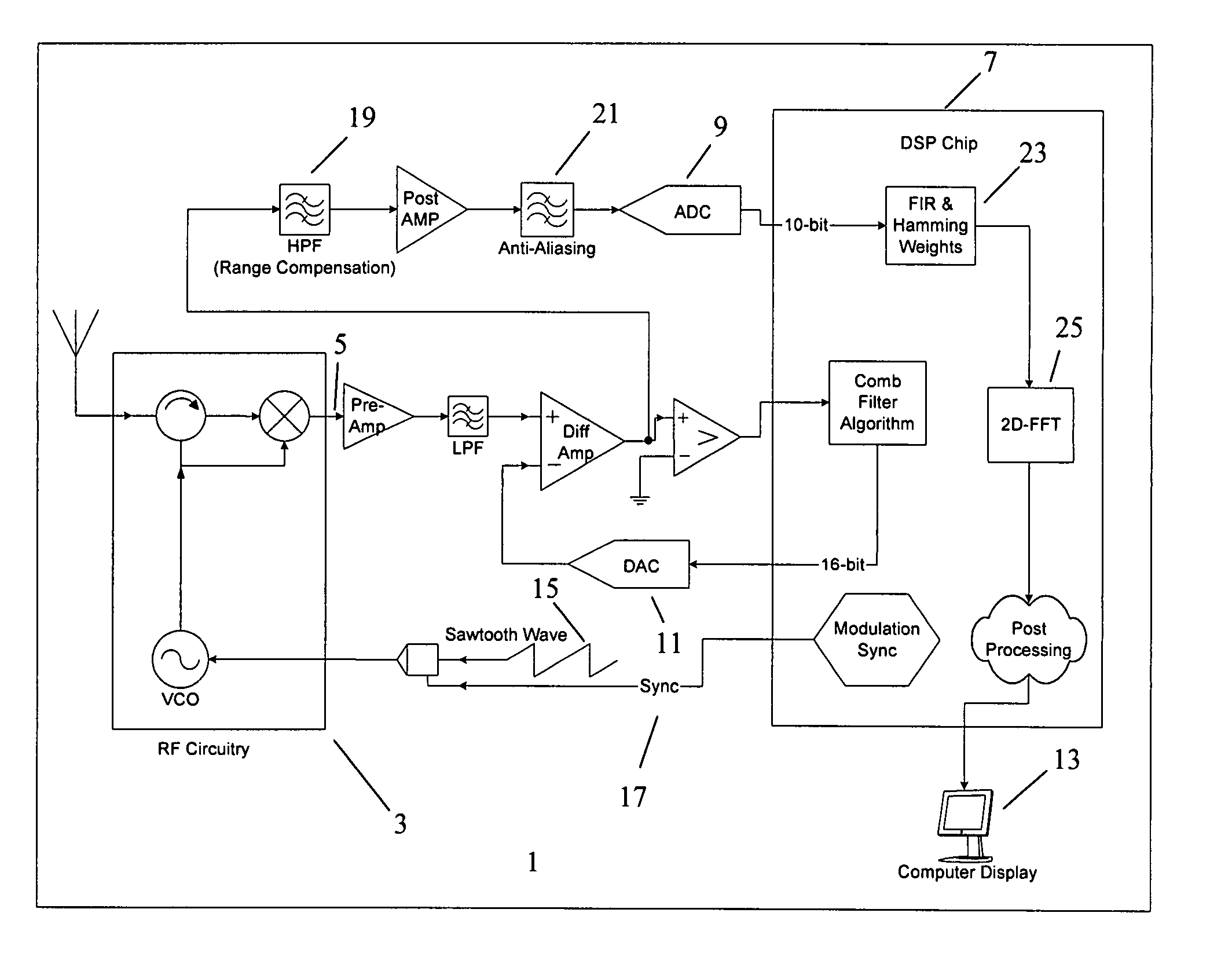
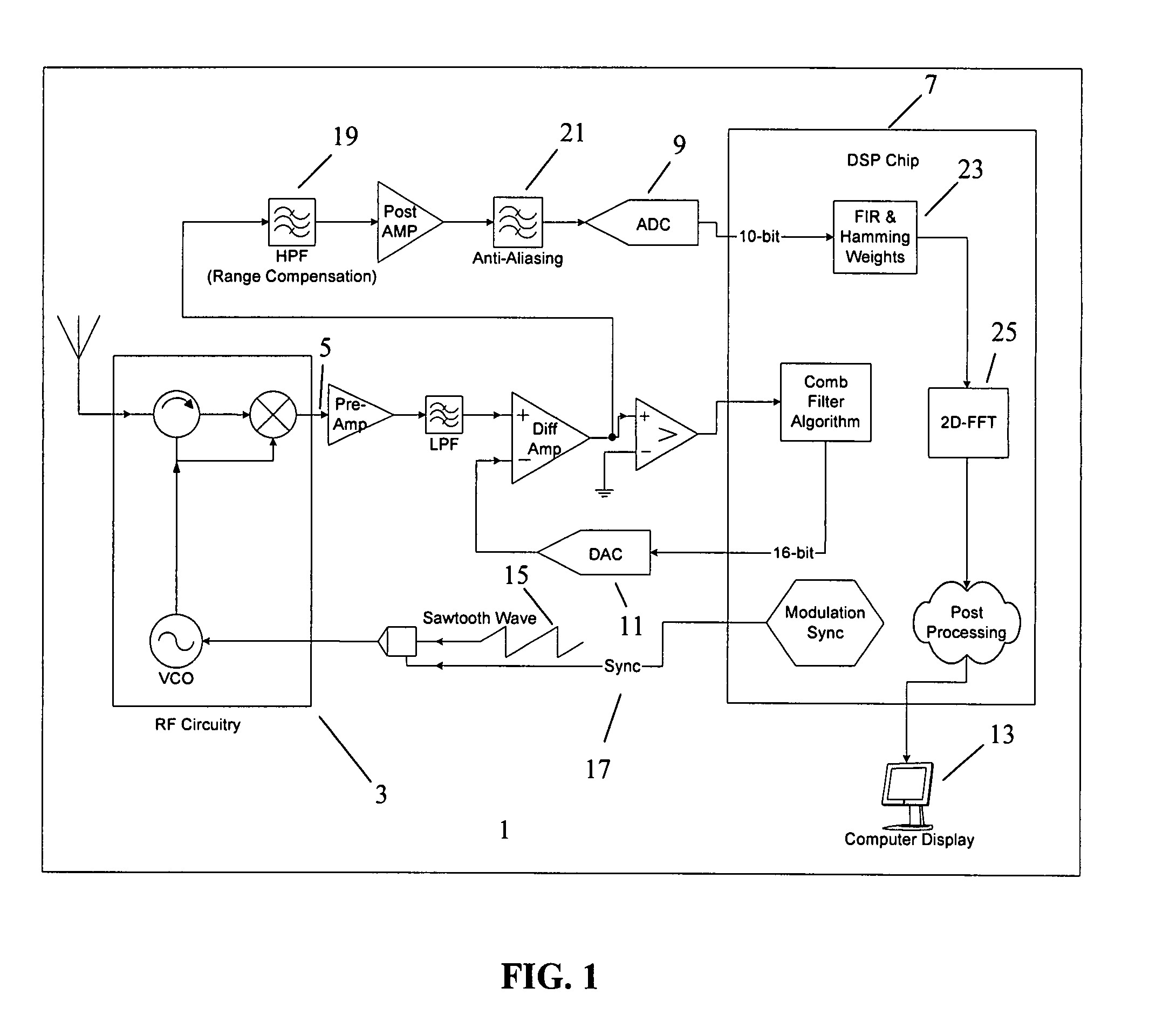
[0031]The block diagram in FIG. 1 shows an embodiment of a FMCW system 1 in accordance with the subject invention. The FMCW system processes a receive signal 5 after homodyne detection 3 in the RF circuitry. Amplification and filtering are done in the analog domain before the signal reaches the digital signal processor (DSP) 7. Amplification and filtering are done while minimizing noise, as the signal strengths are expected to be very low at longer ranges for the detection signal. The DSP can control all of the timing of the system so that all components run off the same system clock and are always in synchronism.

[0032]A key component of this system is the DSP 7. In a specific embodiment, this processor can do all of the Fast Fourier Transform (FFT) processing and can also do any other digital tasks required in the system. In an embodiment, the DSP is flexible and can be programmed quickly and easily. Before the DSP analyzes the receive signal, the receive signal is first amplified ...


PUM


Abstract

The subject invention pertains to a frequency modulation continuous wave (FMCW) radar system. Embodiments relate to methods of improving the performance of such a FMCW system and improving the value of the information provided by such a FMCW system. In an embodiment of the subject invention, the IF level can be monitored while sweeping the frequency of the system through at least a portion of the frequency range of the system. In a specific embodiment, the system is then set to the frequency that produces the minimum IF level, which is the frequency that produces the minimum AM signal level. Embodiments of the invention pertain to techniques for expediting the adaptation of the comb filter to the signal when the system is turned on. In an embodiment, in order to reduce the number of detection calculations a processor performs every frame, a method of quickly determining the largest peaks in the RDM is implemented. Embodiments of the subject invention relate to a method for processing a radar signal that classifies two or more targets. A specific embodiment of a method for processing the radar signal classifies a human target or other target(s) using amplitude values in time-consecutive range-Doppler maps. Embodiments of the invention pertain to a method for processing a radar signal for improving the performance of FMCW detection, tracking, and classification algorithms. Embodiments improve such performance by increasing the SNR and velocity measurement resolution of slow moving targets while minimizing DSP computational and memory requirements in two-dimensional FFT range-velocity processing.

Description

CROSS-REFERENCE TO RELATED APPLICATIONS[0001]The present application claims the benefit of U.S. application Ser. No. 60 / 838,858, filed Aug. 18, 2006 and claims the benefit of U.S. application Ser. No. 60 / 810,487, filed Jun. 1, 2006, both of which are hereby incorporated by reference herein in their entirety, including any figures, tables, or drawings.[0002]The subject invention was made with government support under a research project supported by BAE / Army Research Laboratory, Advanced Sensors Collaborative Technology Alliance (Contract Nos. DAAD 19-01-2-0008 and DAAD 19-01-C-0068).BACKGROUND OF INVENTION[0003]Radar can be used to detect and track targets in a radar scene. Systems for such detecting and tracking can transmit an RF signal onto a radar scene and receive the reflected RF signal from targets and clutter. A common detection technique is homodyne detection. The received signal can then be processed, for example, via digital signal processing (DSP), after amplification and...

Claims


Application Information

Patent Timeline
Patent Type & Authority Applications(United States)
IPC IPC(8): G01S13/00
CPCG01S7/352G01S2007/356G01S13/584G01S13/34G01S7/356
Inventor KURTZ, JAMES LYNNCARLSON, PHILIP RUSSELLOVERMAN, CHARLES HENRY
Owner UNIV OF FLORIDA RES FOUNDATION INC
Why Eureka
Try Eureka