Adaptive transmission and interference cancellation for MIMO radar

Active Publication Date: 2017-06-27
UHNDER INC
View PDF96 Cites 109 Cited by
  • Summary
  • Abstract
  • Description
  • Claims
  • Application Information

AI Technical Summary

Benefits of technology

[0004]The present invention provides methods and a radar system using multiple transmitters and multiple receivers that can mitigate the self-interference present from the multiple transmitters. The self-interference can mask out targets at a further distance than other near targets because of imperfect correla

Problems solved by technology

The sidelobes of the spreading codes used in phase modulated continuous wave (PMCW) radar system

Method used


Image

  • Adaptive transmission and interference cancellation for MIMO radar
  • Adaptive transmission and interference cancellation for MIMO radar
  • Adaptive transmission and interference cancellation for MIMO radar

Examples


Embodiment Construction

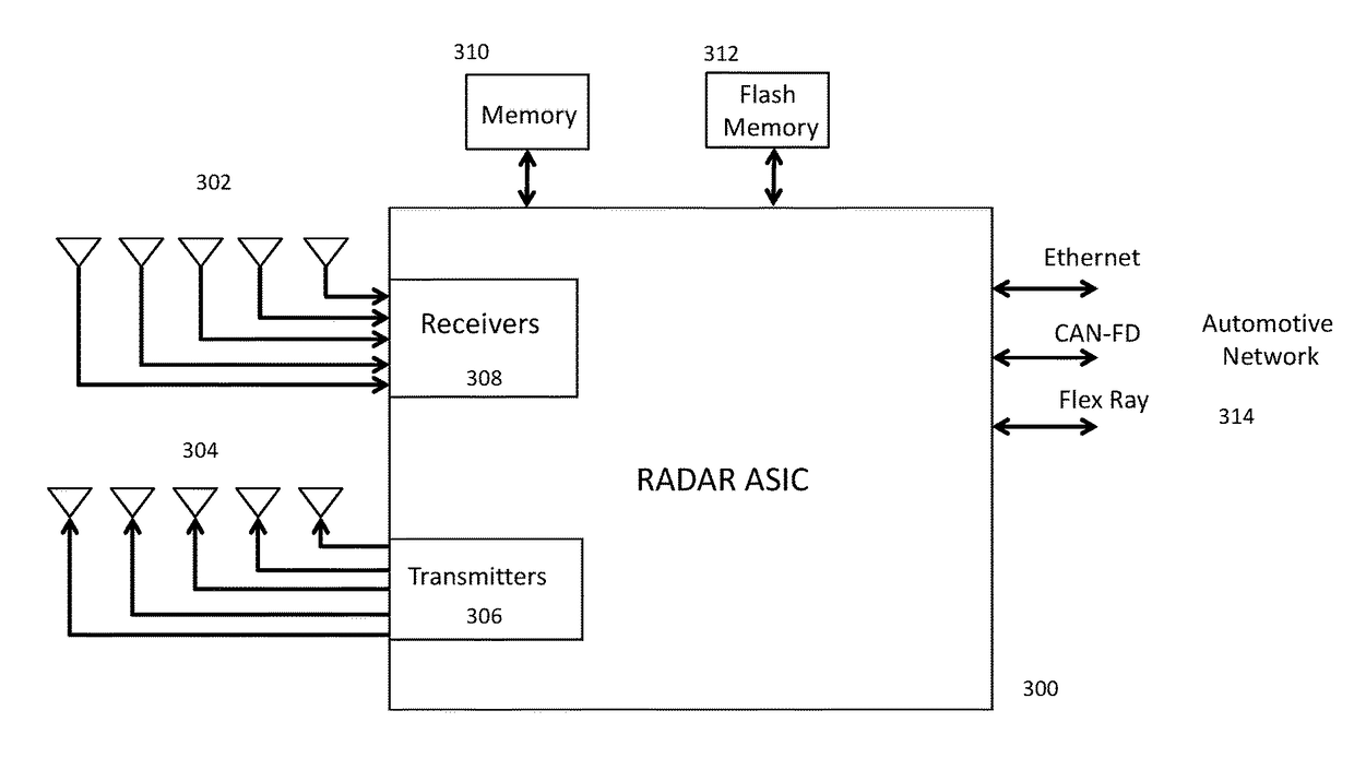
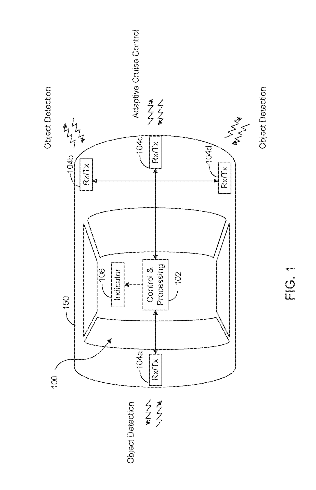
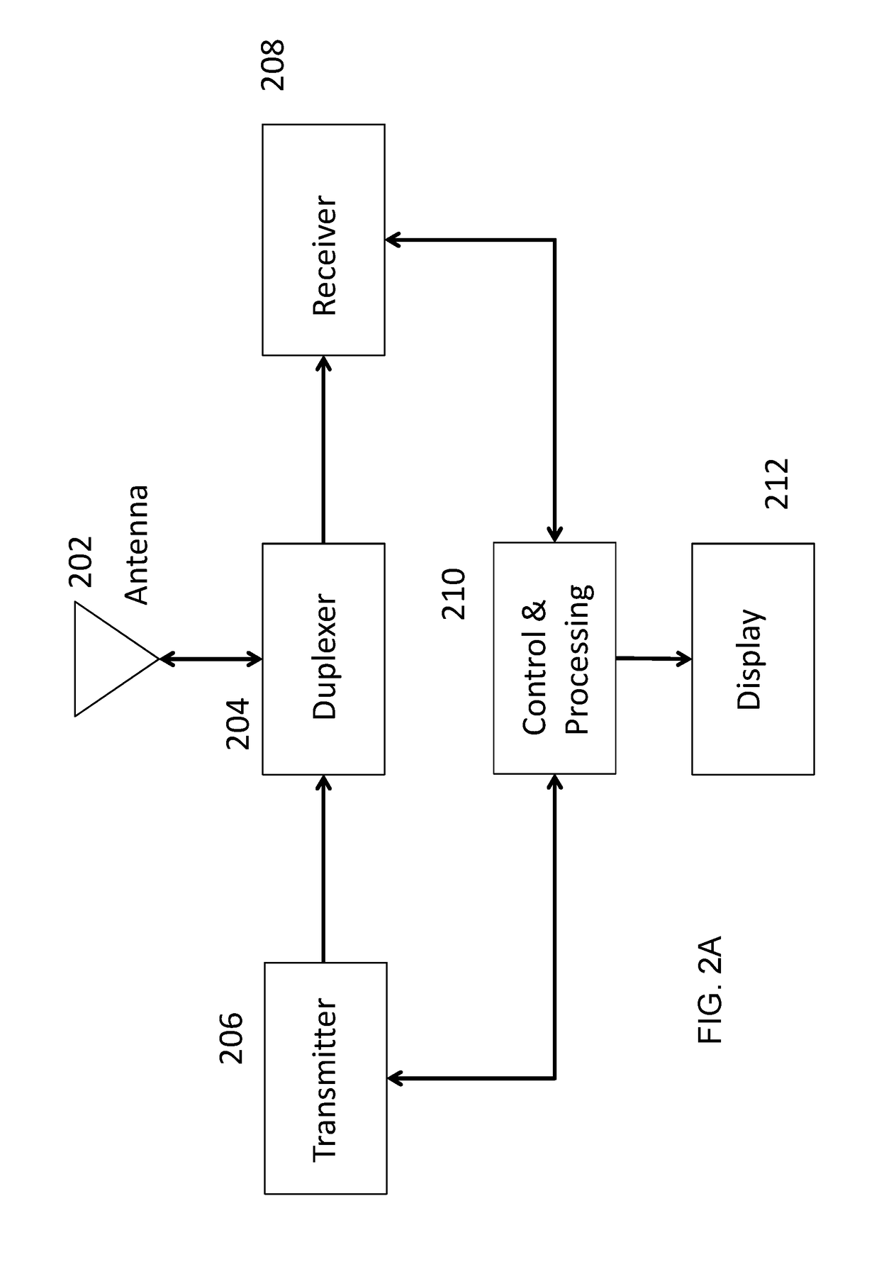
[0021]The present invention will now be described with reference to the accompanying figures, wherein numbered elements in the following written description correspond to like-numbered elements in the figures. Methods and systems of the present invention may achieve better performance from a radar system when there is a near object and a far object. Exemplary embodiments of the present invention accomplish better performance by adjusting the radar system to the environment, the objective and inputs external to the radar system. The invention accomplishes better performance by adapting the radar system under software control.

[0022]The radar sensing system of the present invention may utilize aspects of the radar systems described in U.S. Pat. Nos. 9,575,160 and / or 9,599,702, and / or U.S. patent application Ser. No. 15 / 416,219, filed Jan. 26, 2017, and / or Ser. No. 15 / 292,755, filed Oct. 13, 2016, and / or U.S. provisional applications, Ser. No. 62 / 382,857, filed Sep. 2, 2016, Ser. No. 62...


PUM


Abstract

A radar system has different modes of operation. In one mode the radar operates as a single-input, multiple-output (SIMO) radar system utilizing one transmitted signal from one antenna at a time. Codes with known excellent autocorrelation properties are utilized in this mode. At each receiver the response after correlating with various possible transmitted signals is measured in order to estimate the interference that each transmitter will represent at each receiver. The estimated effect of the interference from one transmitter on a receiver that correlates with a different code is used to mitigate the interference. In another mode, the radar operates as a MIMO radar system utilizing all the antennas at a time. Interference cancellation of the non-ideal cross correlation sidelobes when transmitting in the MIMO mode are employed to remove ghost targets due to unwanted sidelobes.

Description

CROSS REFERENCE TO RELATED APPLICATIONS[0001]The present application claims the filing benefits of U.S. provisional applications, Ser. No. 62 / 319,613, filed Apr. 7, 2016, and Ser. No. 62 / 327,003, filed Apr. 25, 2016, which are hereby incorporated by reference herein in their entireties.FIELD OF THE INVENTION[0002]The present invention is directed to radar systems, and in particular to radar systems for vehicles.BACKGROUND OF THE INVENTION[0003]The use of radar to determine range, velocity, and angle (elevation or azimuth) of objects in an environment is important in a number of applications including automotive radar and gesture detection. A radar typically transmits a radio frequency (RF) signal and listens for the reflection of the radio signal from objects in the environment. A radar system estimates the location and velocity of objects, also called targets, in the environment by comparing the received radio signal with the transmitted radio signal. A radar system with multiple t...

Claims


Application Information

Patent Timeline
IPC IPC(8): G01S13/93G01S7/02H04B17/345H04L27/227H04B7/0413G01S7/40H04B17/309G01S7/292G01S13/931
CPCG01S7/023H04B17/345H04L27/2278G01S13/93H04B7/0413G01S7/4021H04B17/309G01S7/292G01S13/87G01S13/878G01S13/931G01S2013/93272G01S2013/9322G01S2013/9316G01S2013/93271G01S7/0233G01S7/0234
Inventor STARK, WAYNE E.BORDES, JEAN P.DAVIS, CURTISRAO, RAGHUNATH K.MAHER, MONIERHEGDE, MANJUSCHMID, OTTO A.
Owner UHNDER INC
Why Eureka
Try Eureka