MIMO antenna with elevation detection

a technology of elevation detection and input multiple output, which is applied in the direction of antenna details, instruments, antennas, etc., can solve the problems of increasing the number of transmitting and/or receiving antennas, increasing system costs, and more antennas providing better capability at the expense of increased cos

Active Publication Date: 2016-02-04
APTIV TECH LTD
View PDF22 Cites 105 Cited by
  • Summary
  • Abstract
  • Description
  • Claims
  • Application Information

AI Technical Summary

Problems solved by technology

Many ground vehicle (e.g. automotive) radar systems in use today are only able to determine distance and a horizontal or azimuth angle to a target or object.
The number of transmit-antennas and receive-antennas influences the radar spatial capability in azimuth and elevation and also drives system cost.
That is, more antennas provide better capability at the expense of increased cost.
Prior attempts to add elevation resolution

Method used


Image

  • MIMO antenna with elevation detection
  • MIMO antenna with elevation detection
  • MIMO antenna with elevation detection

Examples


Embodiment Construction

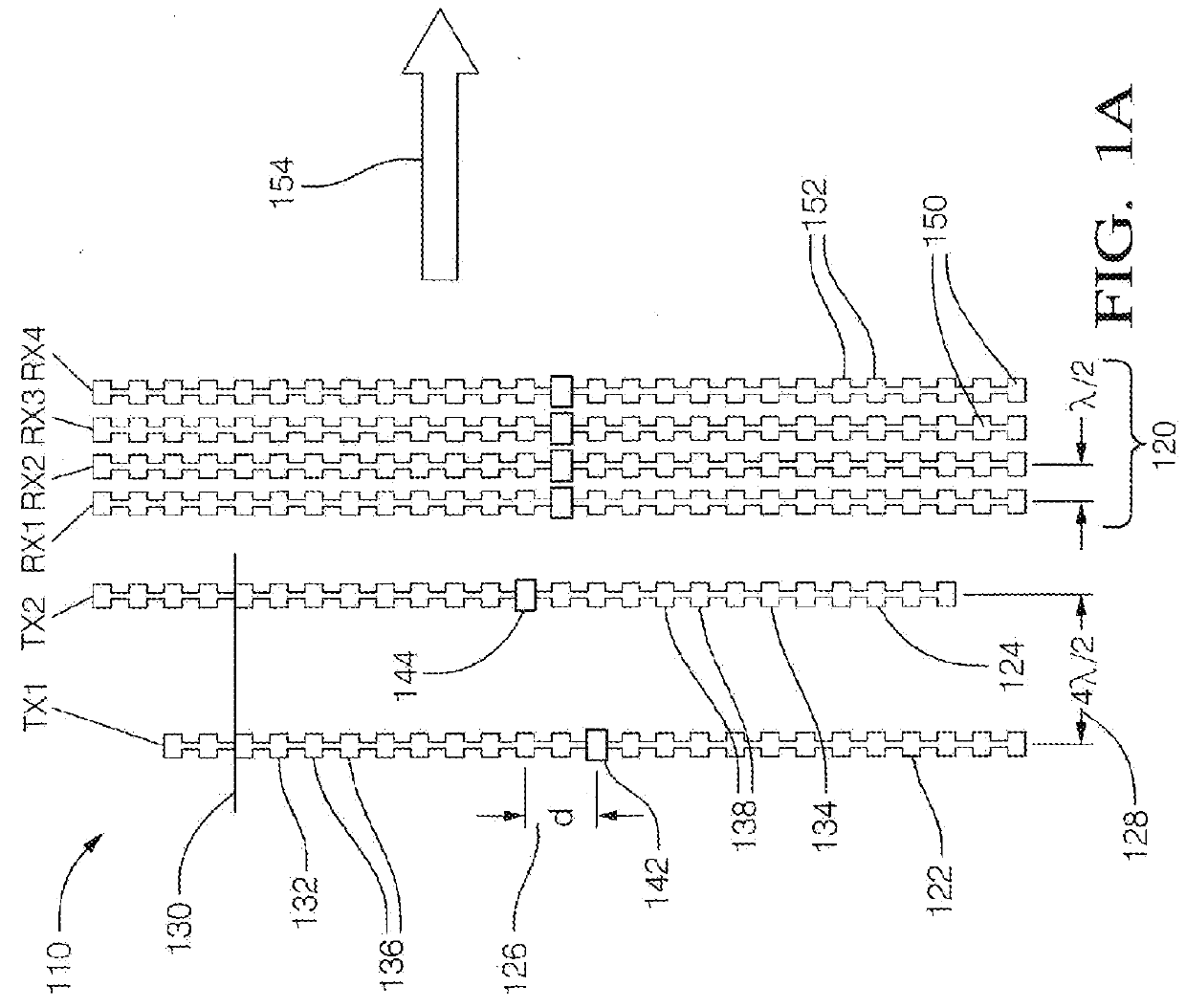
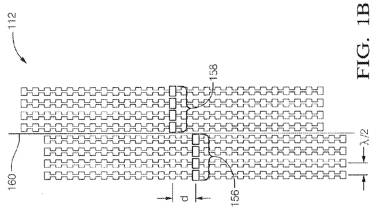
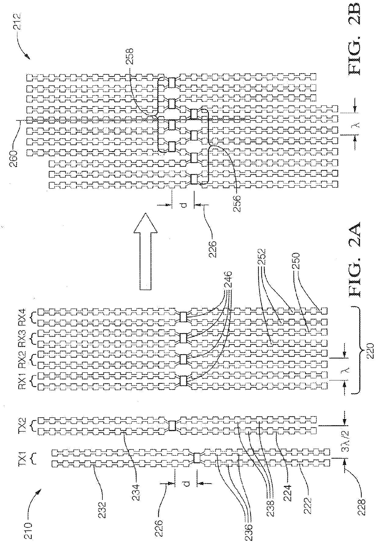
[0027]In general, multiple input, multiple output (MIMO) antenna architectures provide for electronic scanning with improved spatial coverage and resolution. MIMO operation typically requires multiple transmit and multiple receive antennas along with multiple transmitters and receivers. However, the teachings presented herein may also be applicable to a simpler receive antenna configuration, for example, a single receive antenna consisting of a single element. Described herein are various configurations of MIMO antennas where the number of transmit and receive antennas depends on the spatial coverage and resolution required in both the azimuth (horizontal) and elevation (vertical) dimensions. The number of transmitters and receivers can equal the number of transmit and receive antennas, or a fewer number can be timeshared between the respective transmit and / or receiver antennas. However, for best performance, parallel transmit and receive channels are used, one channel per antenna, ...


PUM


Abstract

A multiple input multiple output (MIMO) antenna for a radar system includes a receive antenna, a first transmit-antenna-arrangement, and a second transmit-antenna-arrangement. The receive-antenna is configured to detect radar-signals reflected by a target toward the receive-antenna. The first transmit-antenna-arrangement includes a first vertical-array of radiator elements and a second vertical-array of radiator elements. The first transmit-antenna-arrangement is configured so the first vertical-array can be selectively coupled to a transmitter independent of the second vertical-array. The second transmit-antenna-arrangement includes a third vertical-array of radiator elements and a fourth vertical-array of radiator elements. The second transmit-antenna-arrangement is configured so the third vertical-array can be selectively coupled to a transmitter independent of the fourth vertical-array. The second transmit-antenna-arrangement is vertically offset from the first transmit-antenna-arrangement by a vertical offset distance selected so an elevation angle to the target can be determined by the receive-antenna.

Description

CROSS-REFERENCE TO RELATED APPLICATION[0001]This application is a continuation-in-part application that claims the benefit of U.S. patent application Ser. No. 14 / 197404, entitled MIMO ANTENNA WITH ELEVATION DETECTION, and filed on Mar. 5, 2014, the entire disclosure of which is hereby incorporated herein by reference.TECHNICAL FIELD OF INVENTION[0002]This disclosure generally relates to input multiple output (MIMO) antenna for a radar system, and more particularly relates to vertically offsetting one transmit-antenna from another so an elevation angle to a target can be determined.BACKGROUND OF INVENTION[0003]Many ground vehicle (e.g. automotive) radar systems in use today are only able to determine distance and a horizontal or azimuth angle to a target or object. The transmit-antenna and receive antenna for such a system are typically vertical arrays of radiator and detector elements or patches, respectively. However, it has been recognized that it is desirable to determine a verti...

Claims


Application Information

Patent Timeline
IPC IPC(8): G01S13/44G01S13/931
CPCG01S13/4454G01S7/03G01S7/2813G01S7/2925G01S7/354G01S13/003G01S13/424G01S13/931H01Q21/065H01Q1/3233H01Q21/08
Inventor SEARCY, JAMES F.ALLAND, STEPHEN W.
Owner APTIV TECH LTD
Why Eureka
Try Eureka