
Method of transmitting a precoding matrix in a multi-input multi-output (MIMO) system

a multi-output, multi-input technology, applied in multi-frequency code systems, diversity/multi-antenna systems, polarisation/directional diversity, etc., can solve problems such as difficulty in preparing for subsequent increase in number of antennas, performance could suffer, etc., to achieve less memory and efficient transmission of preceding matrix

Inactive Publication Date: 2009-12-03
LG ELECTRONICS INC
View PDF2 Cites 111 Cited by
  • Summary
  • Abstract
  • Description
  • Claims
  • Application Information

AI Technical Summary

Benefits of technology

[0008]An object of the present invention is to provide a method of transmitting a preceding matrix more efficiently.

Problems solved by technology

Consequently, the performance could suffer.
Here, the number of bits transmitted from the transmitting end not only changes according to the number of antennas, but also has to have a storage (memory) which should be able to store more than 64 matrices, making it inefficient.
At the same time, because the number of reserve W matrices increase exponentially with the increase of the transmitting and receiving antennas, it is difficult to prepare for subsequent increase in number of antennas.

Method used


Image

  • Method of transmitting a precoding matrix in a multi-input multi-output (MIMO) system
  • Method of transmitting a precoding matrix in a multi-input multi-output (MIMO) system
  • Method of transmitting a precoding matrix in a multi-input multi-output (MIMO) system

Examples


Embodiment Construction

[0019]Reference will now be made in detail to the preferred embodiments of the present invention, examples of which are illustrated in the accompanying drawings. Wherever possible, the same reference numbers will be used throughout the drawings to refer to the same or like parts.

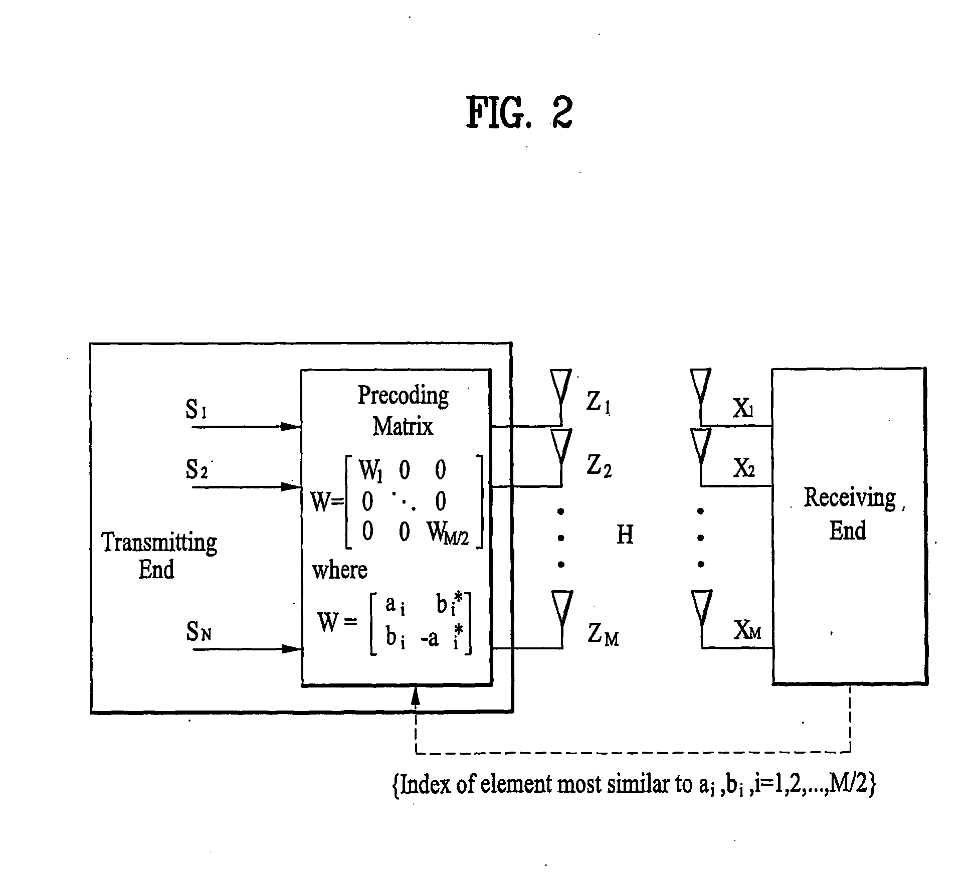
[0020]FIG. 2 is an example illustrating a multi-input, multi-output (MIMO) system according to the present invention. As illustrated in FIG. 2, W matrix can be illustrated according to Equation 1.

W=[W1000⋱000WM2][Equation1]

[0021]In Equation 1,

W1=[a1b1*b1-a1*],

where a* is a conjugate of a. Furthermore, the sub-matrix W is not limited to a 2×2 format, but can be different-sizes, such as 4×4, 8×8, and 16×16.

[0022]In addition, the receiving signal vector x of the receiving end can be expressed according to the following equation.

x=HWs+v  [Equation 2]

[0023]In Equation 2, x is a receiving signal vector, H is a channel matrix, W is a precoding matrix, s is a transmission signal vector before precoding matrix is app...


PUM


Abstract

A method of transmitting a precoding matrix in a multi-input, multi-output (MIMO) system is disclosed. In the system, a receiving end determines feedback information by calculating each diagonal sub-matrix of the precoding matrix. Here, the precoding matrix includes a plurality of sub-matrices arranged in a block diagonal format. Thereafter, the receiving end transmits he feedback information of the each calculated sub-matrix.

Description

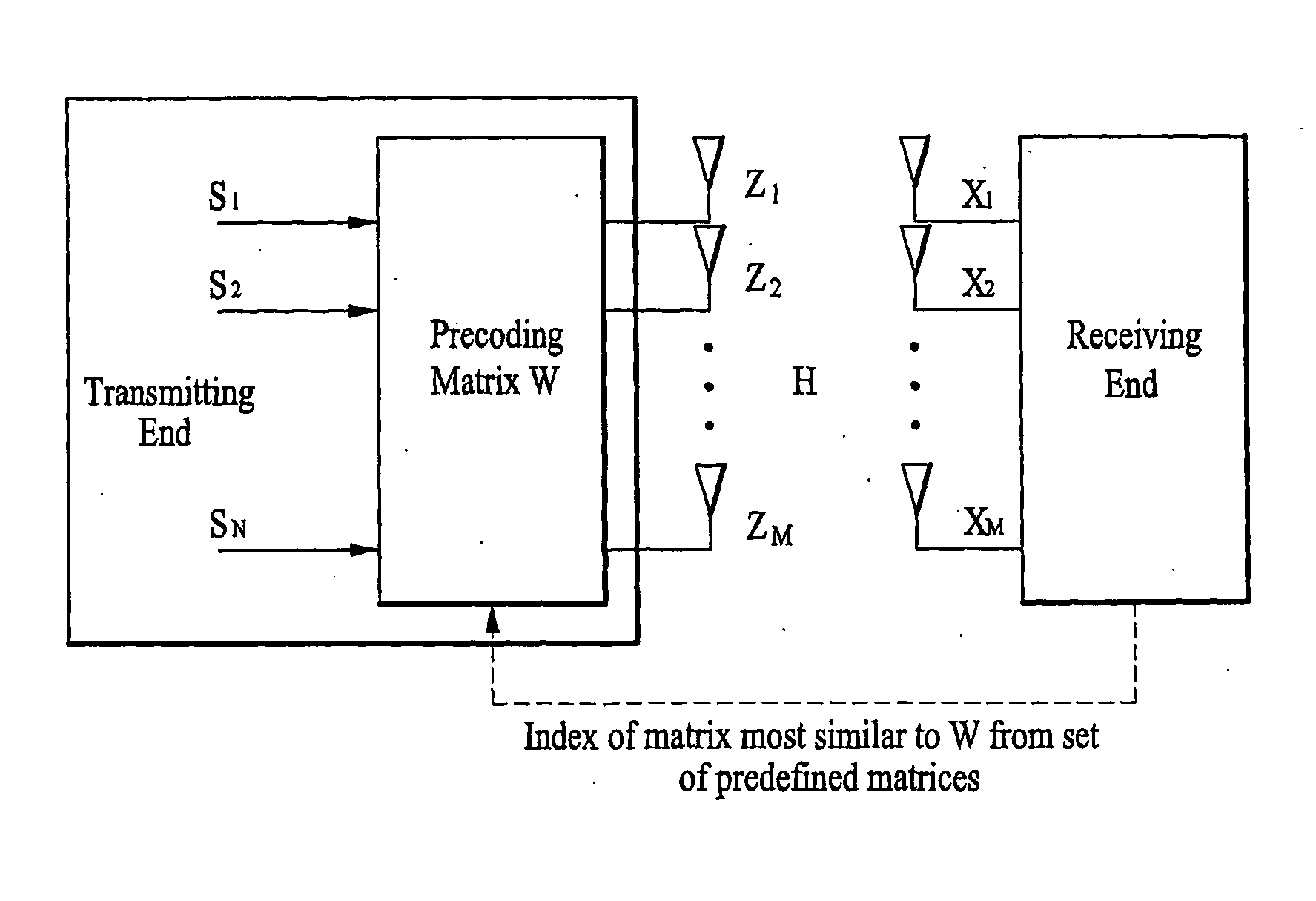
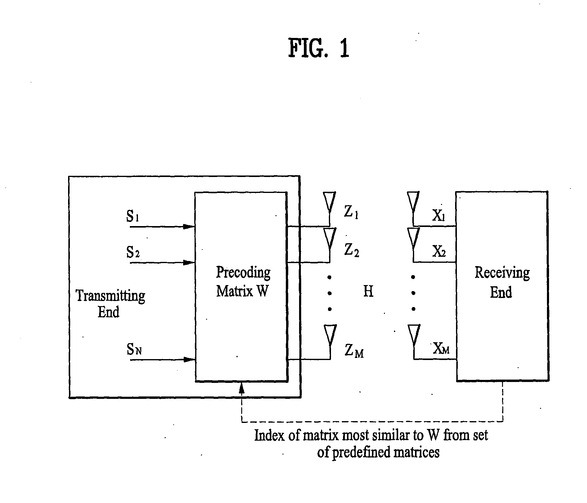
TECHNICAL FIELD[0001]The present invention relates to a method of transmitting a precoding matrix, and more particularly, to a method of transmitting a precoding matrix in a multi-input, multi-output (MIMO) system.BACKGROUND ART[0002]FIG. 1 is an example illustrating a multi-input, multi-output (MIMO) system according to the related art. As illustrated in FIG. 1, in operation, the receiving end uses a channel matrix H to determine a precoding matrix W and transmits (or feeds back) the determined preceding matrix to the transmitting end. At the same time, the transmitting end and the receiving end both possesses a set of matrices, one of which matches or is most similar to the determined precoding matrix W. Thereafter, the receiving end transmits (or feeds back) the index of the matrix which matches or is most analogous to the determined preceding matrix W. Here, the set of indexes corresponding to each of the analogous matrices are referred to as a codebook.[0003]If the transmitting...

Claims


Application Information

Patent Timeline
IPC IPC(8): H04B7/02
CPCH04B7/0417H04B7/0478H04B7/0634H04L2025/03426H04B7/0663H04L25/03343H04B7/0639
Inventor IHM, BIN CHULJIN, YONG SUKCHUN, JIN YOUNG
Owner LG ELECTRONICS INC
Learn More