Prospective control method

A control method and interpolation technology, applied in the direction of program control, computer control, general control system, etc., can solve the problems of increased forward-looking calculation time, cumbersome method, large storage resources of motion control system, etc., to achieve easy computer implementation, extended application Scope and structure scientific and reasonable effect

Active Publication Date: 2020-03-13
湖南戈人自动化科技有限公司
View PDF6 Cites 3 Cited by
  • Summary
  • Abstract
  • Description
  • Claims
  • Application Information

AI Technical Summary

Problems solved by technology

[0004] (1) In order to make the terminal speed of the last section 0, the current control system needs the user to point out that a certain section of trajectory is the last section, which is the case when the user does not know which section is the last section (for example, the trajectory of a small line segment is obtained by visual inspection). obtained by the system), it cannot be used, or there is a jump in the final speed;
[0005] (2) The number of forward-looking segments needs to be determined, which will not only cause the motion control system to require relatively large storage resources, but also need to wait for the next tiny line segment trajectory block to complete the forward-looking calculation before re-interpolation , this defect will reduce the overall efficiency;
[0006] (3) The linking speed between trajectory segments does not take into account the influencing factor that the interpolation cycle can only be an integer multiple. This defect will lead to some trajectory segments whose interpolation cycle is less than 2, or whose initial speed is equal to the running speed and equal to the stop speed. When planning, the actual planned start speed or stop speed deviates, which leads to a sudden change in the speed during interpolation and affects the machining accuracy;
[0007] (4) When the angle between two adjacent straight-line trajectory segments is extremely small, there is no fitting process, which will increase the forward-looking calculation time and reduce the processing efficiency, but this method is too cumbersome

Method used

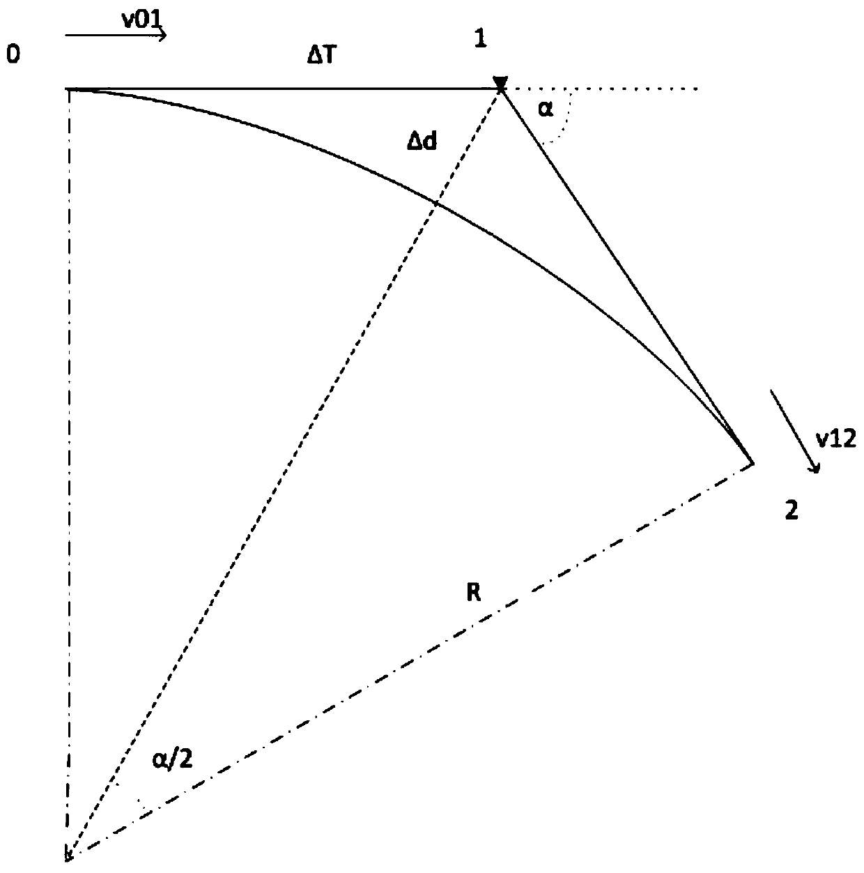
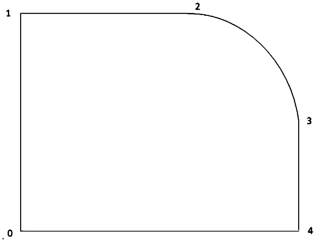
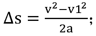

Image

  • Prospective control method
  • Prospective control method
  • Prospective control method

Examples


Embodiment

[0024] Example: such as figure 1 As shown, the present invention provides a technical solution: a forward-looking control method, including arbitrary interpolation curves including tiny line segments, specifically including the following steps:

[0025] S1. Calculate the maximum velocity v1 at the inflection point at the end point of the interpolation curve, add the angle at the inflection point to form a constraint, and perform curve interpolation under this constraint;

[0026] According to the above technical solution, the maximum speed of the inflection point in step S1 has the following constraints:

[0027] 1) Trajectory allowable error, set to Δd_max;

[0028] 2) Interpolate the maximum acceleration a;

[0029] 3) Interpolate the maximum velocity v_max.

[0030] According to the above-mentioned technical scheme, the principle of acceleration and deceleration of the curve interpolation linear velocity is: according to the current linear velocity, the uniform decelerat...


PUM


Abstract

The invention discloses a prospective control method, which is suitable for any interpolation curve including a micro line segment, and specifically comprises the following steps of: calculating the maximum speed v1 at an inflection point of an end point of the interpolation curve, adding an included angle at the inflection point to form a constraint, and performing curve interpolation under the constraint, wherein the target interpolation point of the last point of the curve interpolation is not the end point of the curve, but the midpoint of the real track arc; acceleration and decelerationcontrol of curve interpolation ensures that the speed of reaching the last point of the interpolation end point is just v1. The method is scientific and reasonable in structure, safe and convenient touse, scientific and reasonable, simple in calculation and easy to implement by a computer. According to the prospective control method, any interpolation curve including a micro line segment is greatly expanded.

Description

technical field [0001] The invention relates to the technical field of numerical control systems and robot control systems, in particular to a forward-looking control method. Background technique [0002] The processing of workpieces with complex surfaces generally resolves the surface curves into a large number of straight lines or arcs, including tiny line segments, and then realizes trajectory processing by means of linear interpolation or arc interpolation through the motion control system, and the speed of tiny line segments Control is of great significance. It not only directly affects the processing quality and processing efficiency of the workpiece, but also affects the life of the processing equipment. If the feed speed of each tiny line segment is accelerated from zero and then decelerated to zero, the average feed rate will be greatly reduced. In addition, frequent acceleration and deceleration will also reduce the surface quality of the processed workpiece, incre...

Claims


Application Information

Patent Timeline
Patent Type & Authority Applications(China)
IPC IPC(8): G05B19/4065
CPCG05B19/4065G05B2219/37616
Inventor 胡小春
Owner 湖南戈人自动化科技有限公司
Why Eureka
Try Eureka