
Engine cooling system

A technology of engine cooling and mechanical water pump, which is applied in the direction of engine cooling, engine components, machine/engine, etc. It can solve the problem that the engine is difficult to reach the normal operating temperature as soon as possible, so as to reduce the heat dissipation, ensure the effect of warm air, and improve the heating effect. The effect of machine speed

Active Publication Date: 2020-03-17
ANHUI JIANGHUAI AUTOMOBILE GRP CORP LTD
View PDF5 Cites 3 Cited by
  • Summary
  • Abstract
  • Description
  • Claims
  • Application Information

AI Technical Summary

Problems solved by technology

[0003] The main purpose of the present invention is to propose an engine cooling system, which aims to solve the problems in the prior art that it is difficult to reach the normal operating temperature as soon as possible when the engine is just started.

Method used


Image

  • Engine cooling system
  • Engine cooling system
  • Engine cooling system

Examples


Embodiment Construction

[0025] The following will clearly and completely describe the technical solutions in the embodiments of the present invention with reference to the accompanying drawings in the embodiments of the present invention. Obviously, the described embodiments are only part of the embodiments of the present invention, not all of them. Based on the embodiments of the present invention, all other embodiments obtained by persons of ordinary skill in the art without creative efforts fall within the protection scope of the present invention.

[0026] It should be noted that if there is a directional indication (such as up, down, left, right, front, back...) in the embodiment of the present invention, the directional indication is only used to explain the position in a certain posture (as shown in the accompanying drawing). If the specific posture changes, the directional indication will also change accordingly.

[0027] In addition, if there are descriptions involving "first", "second" and ...


PUM


Abstract

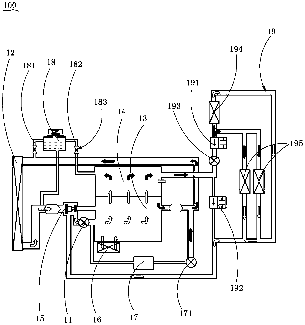
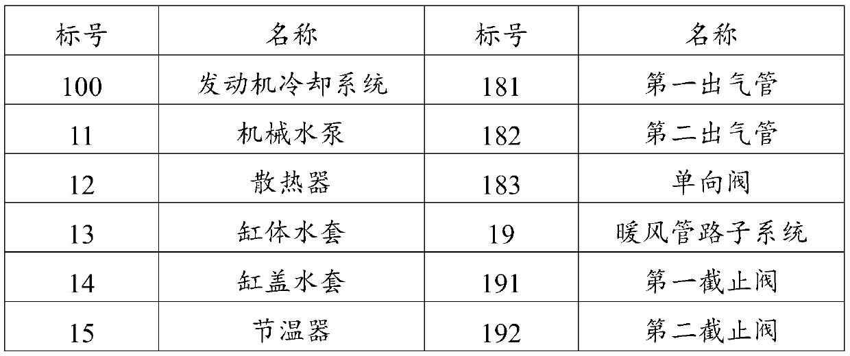
The invention discloses an engine cooling system which comprises a thermostat, a mechanical water pump, a radiator, a cylinder block water jacket, a cylinder cover water jacket and a warm air pipelinesubsystem, wherein the mechanical water pump, the cylinder block water jacket and the radiator form a complete water path circulation; the thermostat is arranged between the mechanical water pump andthe radiator and is used for controlling on-off between the mechanical water pump and the radiator; the cylinder block water jacket communicates with the cylinder cover water jacket; the water outletof the cylinder cover water jacket communicates with the water inlet of the warm air pipeline subsystem; the water outlet of the warm air pipeline subsystem communicates with the water inlet of the mechanical water pump; a first stop valve is arranged between the cylinder cover water jacket and the warm air pipeline subsystem and is used for controlling on-off between the cylinder cover water jacket and the warm air pipeline subsystem. When the engine is at a low temperature, the radiator and the warm air pipeline subsystem do not participate in circulation, and radiating devices are reduced,so that the engine can reach the normal working temperature as quickly as possible.

Description

technical field [0001] The invention relates to the technical field of engines, in particular to an engine cooling system. Background technique [0002] The main function of the engine cooling system is to keep the engine within the proper temperature range under all operating conditions. After the cold engine is started, the cooling system must ensure that the engine heats up quickly and reaches the normal operating temperature as soon as possible. During the working period of the engine, due to the heating effect of the high-temperature gas, the temperature of the engine components is high. If proper cooling is not carried out, the power, economy, reliability and durability of the engine will eventually be reduced in an all-round way. In the prior art, the engine cooling system is also connected to the warm air pipeline. When the engine is just started, because the warm air pipeline disperses heat, it is difficult for the engine cooling system to reach the normal operatin...

Claims


Application Information

Patent Timeline
IPC IPC(8): F01P5/10F01P3/02F01P11/00F01P7/14B60H1/00B60H1/06
CPCB60H1/00271B60H1/06B60H2001/00307F01P3/02F01P5/10F01P7/14F01P11/00F01P2003/028F01P2007/146F01P2060/02F01P2060/04
Inventor 王杰刚侯亦波张雪林韦平张增光豆刚冯玮玮滕建耐金奎阮仁宇张良超杨冰胡宏德傅豪
Owner ANHUI JIANGHUAI AUTOMOBILE GRP CORP LTD
Learn More