
Sounding device and electronic terminal

A sounding device and combined technology, applied in the direction of electrical components, telephone structures, electromechanical sensors, etc., can solve the problems of increasing the pulling force of the front cover and the shell, long design and change cycle, high cost, etc., to achieve superior sealing performance, Simple molding and improved pull-out force

Active Publication Date: 2020-03-17
GOERTEK INC
View PDF6 Cites 1 Cited by
  • Summary
  • Abstract
  • Description
  • Claims
  • Application Information

AI Technical Summary

Problems solved by technology

However, since the double-shot injection molding sealing ring can only be injected with specific raw materials and specific machines, the cost is expensive and the design and change cycle is long and debugging is difficult. Those skilled in the art try to combine the elastic seal on the front cover. , the elastic seal can be formed on the side of the front cover by hot pressing, etc. At this time, the elastic seal occupies the position of the corner of the front cover, so it is no longer possible to increase the size of the front cover and the shell by setting a hot-melt column at the corner Technical purpose of pull-out force

Method used


Image

  • Sounding device and electronic terminal
  • Sounding device and electronic terminal
  • Sounding device and electronic terminal

Examples


Embodiment 1

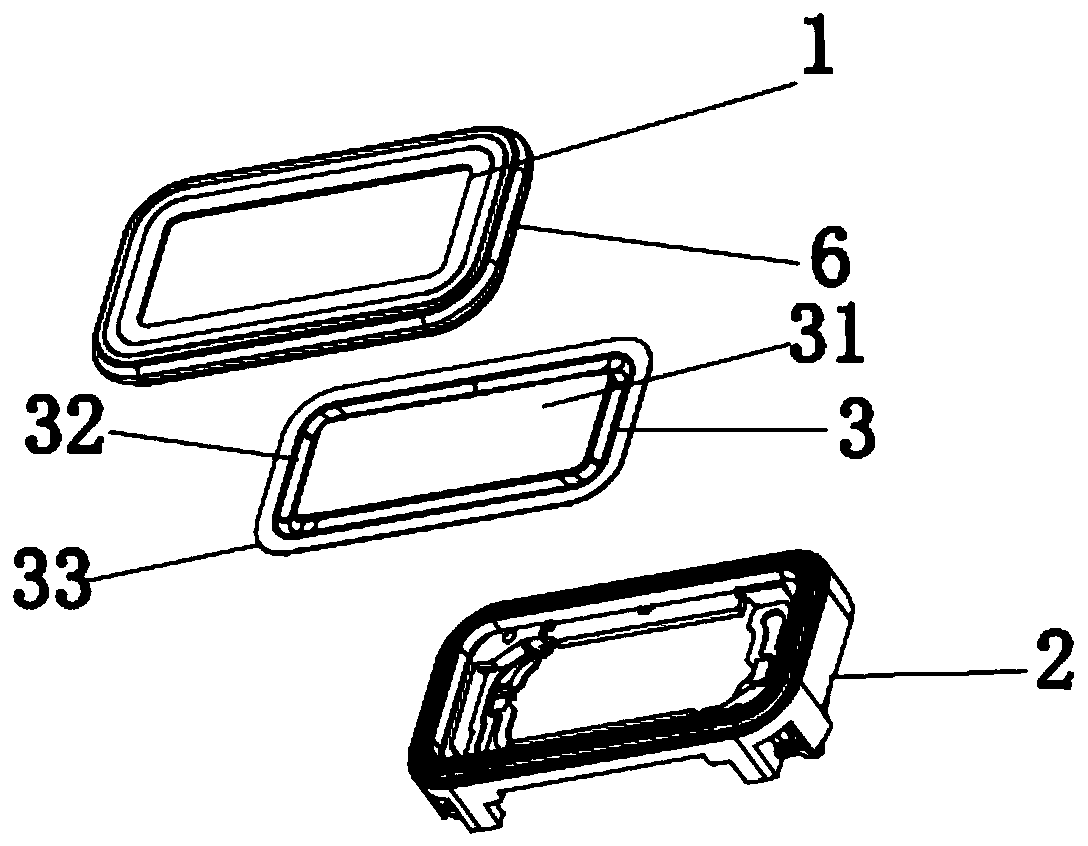
[0046] see image 3 , Figure 4 and Figure 5Commonly shown, a sounding device is provided, which specifically includes a front cover 1 and a housing 2 that are combined together. The cavity surrounded by the front cover 1 and the housing 2 accommodates a diaphragm 3, and the front cover 1 is far away from the diaphragm 3. The surface is covered with an elastic seal 6 , and the elastic seal 6 is integrated with the front cover 1 .

[0047] Specifically, the upper surface of the front cover 1 away from the diaphragm 3 is covered with an elastic seal 6. The present invention arranges the elastic seal 6 on the front cover 1. On the one hand, the elastic seal 6 can realize the sealing of the sound-generating device and improve the sound quality. The sealing and waterproofing of the sounding device; on the other hand, when the sounding device is assembled into the electronic terminal, the assembly of the sounding device and the electronic terminal is realized by compressing the e...

Embodiment 2

[0056] Compared with the first embodiment, this embodiment has the same point, the first glue-coating area 41 is set at the junction of the front cover 1 and the edge part 33 of the diaphragm, the difference is that in this embodiment, the concave part 421 is disposed on the housing 2 , the protruding portion 422 is disposed on the front cover 1 , the protruding portion 422 is inserted into the recessed portion 421 , and is fixed together by the glue in the recessed portion 421 . In fact, the main function of this part of the design is equivalent to the design of the second glue application area 42 in the first embodiment.

[0057] As mentioned in the first embodiment, the joints of the front cover 1 , the casing 2 and the edge portion 33 of the diaphragm are all provided with a first glue-receiving groove 51 , which will not be repeated here.

[0058] In addition to the setting of the above-mentioned gluing area and the gluing tank, in this embodiment, as Figure 8 As shown,...


PUM


Abstract

The invention discloses a sounding device and an electronic terminal. The sounding device comprises a front cover and a shell which are combined together; a vibrating diaphragm is installed in a cavity defined by the front cover and the outer shell, an elastic sealing piece is integrally combined on the front cover, a step structure matched with the front cover and the outer shell is formed on theassembling face of the front cover and the outer shell, at least one gluing area is arranged on the step structure, the gluing area is configured to be used for containing glue, and the front cover and the outer shell are bonded and fixed through the glue. The sounding device not only has good sealing performance, but also is simple in assembly process; meanwhile, the drawing force of the front cover and the shell is improved in a gluing mode, the combination firmness degree of the front cover and the shell can be effectively enhanced, and glue overflowing is prevented.

Description

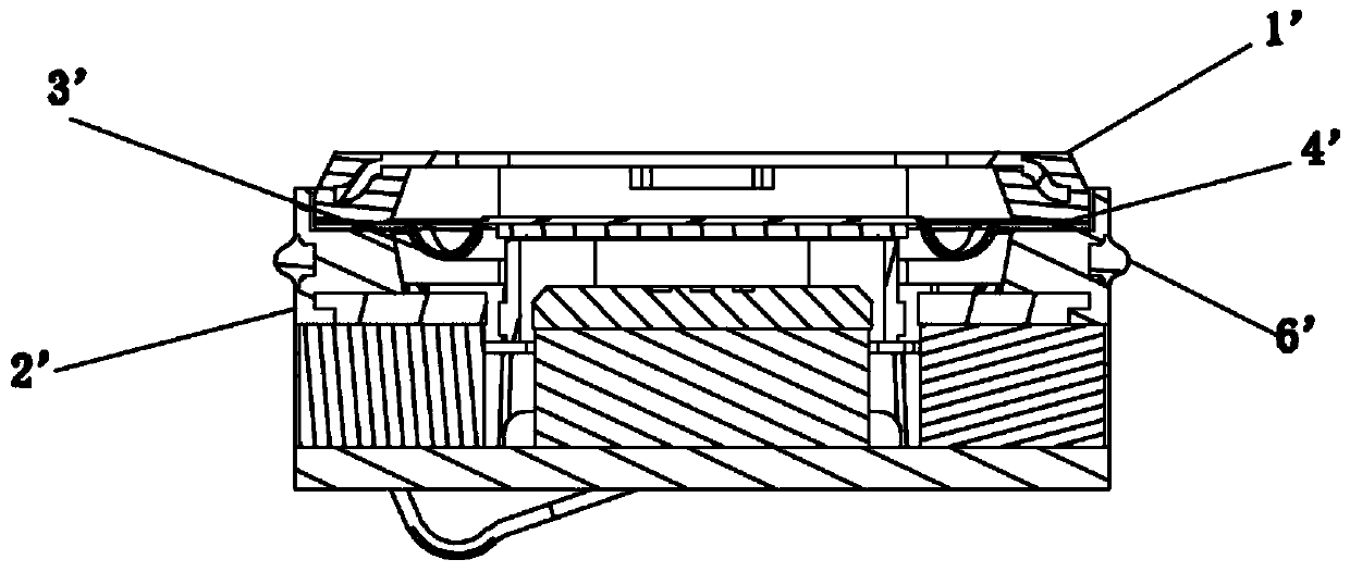
technical field [0001] The present invention relates to the technical field of electroacoustic products, and more specifically, to a sound generating device and an electronic terminal. Background technique [0002] Smartphones and other electronic terminals will integrate a sounding device, but when the sounding device is assembled with the electronic terminal, in order to prevent water from entering the electronic terminal through the gap between the sounding device and the housing of the electronic terminal, causing the function of the electronic terminal to fail, the sounding device needs to be adjusted. The gap between the device and the housing is sealed. [0003] A sealing method is provided in the prior art, such as figure 1 and 2 As shown, the soft rubber (elastic seal 6') and the housing 2' are formed by double-shot injection molding, the front cover 1' and the diaphragm 3' are bonded through the glue-coating area 4', and at the same time, the outer ring of the fr...

Claims


Application Information

Patent Timeline
Patent Type & Authority Applications(China)
IPC IPC(8): H04M1/03H04R7/00
CPCH04M1/03H04R7/00
Inventor 韩志磊孔德刚朱婷左安良
Owner GOERTEK INC
Learn More