
Locking device for foundry sand box

A technology of locking device and sand box, which is applied in the direction of casting molding equipment, molding box, manufacturing tools, etc., can solve the problems that affect the stability and service life of casting processing, the difficulty of removing nuts and screws, and the inability to continue to use. Achieve fast and effective separation, good practicability, and reasonable structure settings

Active Publication Date: 2021-01-29
正阳县精工机械有限责任公司
View PDF5 Cites 0 Cited by
  • Summary
  • Abstract
  • Description
  • Claims
  • Application Information

AI Technical Summary

Problems solved by technology

However, this traditional method has a defect. When the liquid metal is poured into the flask, the temperature of the flask will rise rapidly causing the flask to expand, and the expanded flask will lock the nut and the screw. After removing the nut and Extremely difficult when screwing
Moreover, when the expansion force of the sand box on the nut and the screw is too large, the screw may be bent and deformed, making it impossible to continue to use, which will affect the stability and service life of the casting process, and the applicability is strong and the practicability is limited.

Method used


Image

  • Locking device for foundry sand box
  • Locking device for foundry sand box
  • Locking device for foundry sand box

Examples


Embodiment 1)

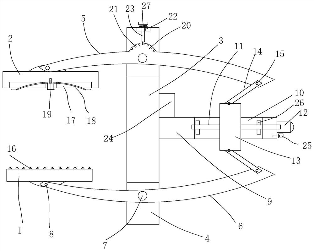
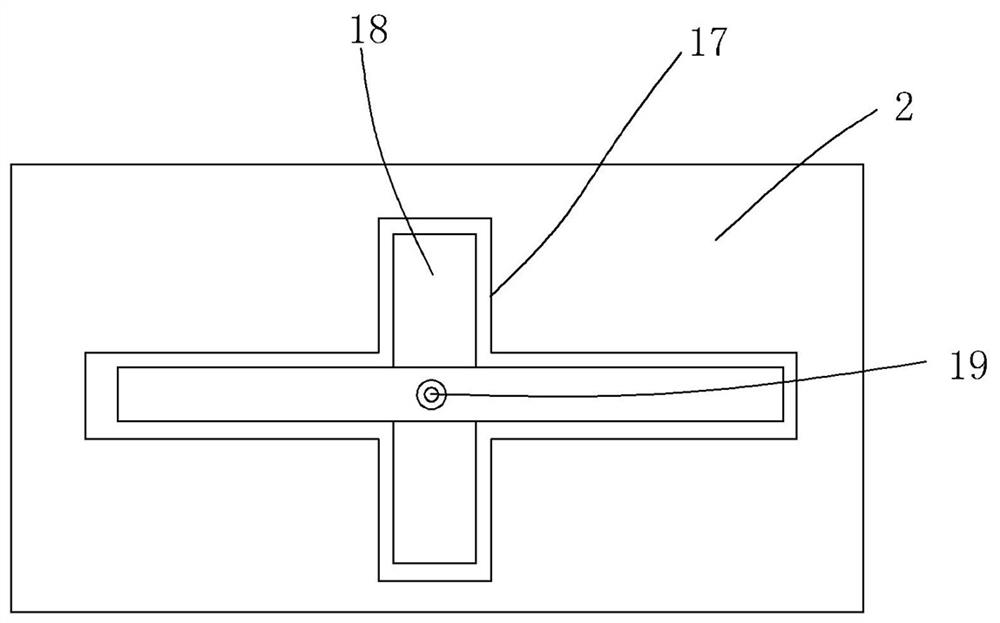
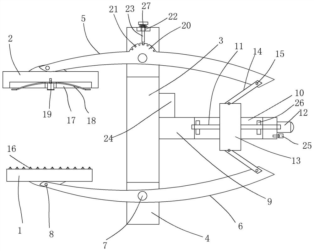
[0015] figure 1 and figure 2 A specific embodiment of the invention is shown in which figure 1 It is a structural schematic diagram of the present invention; figure 2 It is a structural schematic diagram of another viewing angle of the clamping platen in the present invention.

[0016] See figure 1 and figure 2 , a locking device for a foundry flask, comprising a load-bearing bottom plate 1 for pressing against the bottom of the lower flask and a clamping plate 2 for clamping and pressing on the top of the upper flask, and a vertical strut 3 is also provided. The bottom surface and the top surface of the vertical struts are all provided with strip-shaped grooves 4, and the top and bottom of the vertical struts are respectively provided with upturned rods 5 and downturned rods 6, and the upturned rods and downturned rods The middle part of the rod is respectively connected in the strip-shaped grooves on the top surface and the bottom surface of the vertical support rod ...


PUM


Abstract

The invention discloses a locking device for a casting sand box, which includes a bearing bottom plate for pressing against the bottom surface of the lower sand box, a clamping plate for clamping and pressing on the top surface of the upper sand box, and a vertical support rod. Both the bottom surface and the top surface of the vertical strut are provided with strip-shaped grooves, and the top and bottom of the vertical strut are respectively provided with upturned rods and downward warped rods. The middle part of the transverse support plate is provided with an up and down transparent adjustment groove, and a ball screw is arranged in the adjustment groove, and a small motor is fixed at the end of the transverse support plate, and a slide screw threaded with the ball screw is arranged in the adjustment groove. block, the outer ends of the upturned rod and the downturned rod are connected to the top surface and the bottom surface of the slide block through ribs. The structure setting of the present invention is reasonable, which can effectively and quickly realize the clamping and locking of the casting lower sand box and the upper sand box, which is not easy to be stuck, and can also quickly and effectively realize the quick and effective clamping and locking of the bearing base plate and the clamping pressure plate. Separation, strong applicability and good practicability.

Description

technical field [0001] The invention belongs to the technical field of supporting equipment for casting sand boxes, and in particular relates to a locking device for casting sand boxes. Background technique [0002] In the traditional casting field, there are lock box holes on the flange sides of the upper sand box and the lower sand box respectively, and the upper sand box and the lower sand box use screws, nuts and gaskets to lock the upper sand box and the lower sand box. tight. However, this traditional method has a defect. When the liquid metal is poured into the flask, the temperature of the flask will rise rapidly causing the flask to expand, and the expanded flask will lock the nut and the screw. After removing the nut and Extremely difficult when screwing. Moreover, when the expansion force of the sand box that the nut and the screw rod are subjected to is too large, the screw rod may be bent and deformed, making it impossible to continue to use, thereby affecting...

Claims


Application Information

Patent Timeline
Patent Type & Authority Patents(China)
IPC IPC(8): B22C21/08
CPCB22C21/08
Inventor 林义
Owner 正阳县精工机械有限责任公司
Learn More