A multi-beat screw counting machine and screw counting feeding method
What is AI technical title?
AI technical title is built by Patsnap AI team. It summarizes the technical point description of the patent document.
A counting machine and screw technology, which is applied in the field of multi-beat screw counting machine and screw counting feeding, to achieve the effect of reducing the sticking rate, reducing the counting error rate and preventing counting errors
Active Publication Date: 2021-10-26
重庆聿远机器人科技有限公司
View PDF6 Cites 0 Cited by
Summary
Abstract
Description
Claims
Application Information
AI Technical Summary
This helps you quickly interpret patents by identifying the three key elements:
Problems solved by technology
Method used
Benefits of technology
Problems solved by technology
However, the current screw counting equipment cannot meet the above requirements, and special non-standard structural design is required
Method used
Image
Click on the blue label to locate the original text in one second.
Reading with bidirectional positioning of images and text.
Examples
Embodiment 1
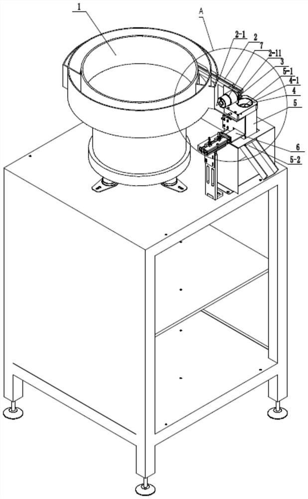
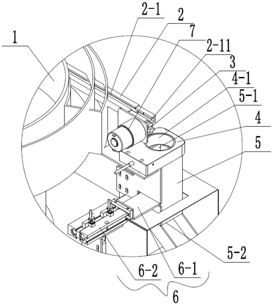
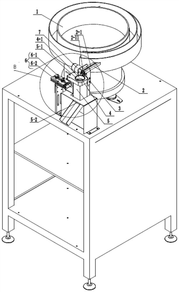
[0052] Embodiment one: see Figure 1-14 , a multi-beat screw counting machine, including a screw vibrating plate 1, a screw conveyor track 2, a distribution gear 3, an annular proximity sensor 4, a temporary storage bin 5 and a discharge switch valve 6.
[0053] Preferably, the screw vibrating plate 1 adopts an equally divided helical top plate. If you can choose the Hy-060 screw vibrating plate produced by Dongguan Hongyang Automation Equipment Co., Ltd. see Figure 1-4 One end of the screw conveying track 2 is connected to the outlet of the screw vibrating plate 1, the distribution gear 3 is arranged on the other end of the screw conveying track 2 and when the distribution gear 3 rotates, the screws at the other end of the screw conveying track 2 can be screwed one by one. Dial out; the distribution gear 3 is connected to the first rotary power source 7, and the first rotary power source 7 is used to drive the distribution gear 3 to rotate. Specifically, the screw conveyi...
Embodiment 2
[0074] Embodiment two: a screw counting feeding method, which uses the multi-beat screw counting machine described in embodiment one, the method includes the following steps:
[0075] S100, installing screws in the screw vibrating plate 1;
[0076] S200, set the screw feeding formula (specifically, four setting values 5, 4, 7, 3 can be input respectively through the touch screen); the screw feeding formula includes the number of screw feeding in the first beat (such as 5 screws) , The number of screw feeds in the second beat (such as 4 screws), the number of screw feeds in the third beat (such as 7 screws), the number of screw feeds in the fourth beat (such as 3 screws), and repeat the cycle in turn;
[0077] S310, the PLC controls the discharge switch valve 6 to start work and makes the discharge port 5-2 of the temporary storage bin 5 in a closed state (see Figure 10-11 );
[0078] S320, the PLC controls the screw vibrating plate 1 to start working, and the screw vibrat...
PUM
Abstract
The invention discloses a multi-beat screw counting machine, which is characterized in that it includes a screw vibrating plate, a screw conveying track, a distribution gear, an annular proximity sensor, a temporary storage bin and a discharge switch valve; the distribution gear is arranged on the screw The other end of the conveying track and the screws at the other end of the screw conveying track can be dialed out one by one; the sensing hole of the annular proximity sensor is used to count the screws dialed out by the distribution gear, and the material receiving port at the upper end of the temporary storage bin is used The screw that falls in the sensing hole that receives the annular proximity sensor; the discharge switch valve is used to control the opening or closing of the discharge port at the lower end of the temporary storage bin; the screw vibration plate, the first rotating power source, the annular proximity Both the sensor and the discharge switch valve are electrically connected to the PLC. The present invention can realize the different requirements of screw feeding quantity in each beat, and can repeat the cycle in sequence, and can realize multi-beat screw counting and feeding in sequence and cyclic work. The invention also discloses a screw counting feeding method.
Description
technical field [0001] The invention belongs to a multi-beat screw counting machine and a screw counting feeding method. Background technique [0002] In order to meet the customer's non-standard production needs (such as in the automatic assembly of car seats), the screws are required to be counted in multiple beats and then fed and cycled repeatedly. At the same time, the screw sticking rate is required to be 0.1‰ and the counting error rate is 0.1‰. For example, the required screw feeding formula is: such as: 5 for the first time, 4 for the second time, 7 for the third time, 3 for the fourth time, and then repeat 5, 4, 7, 3 and Continue to repeat the cycle sequentially. In view of the fact that the number of screw feeds per beat is not equal, and the cycle is repeated, correspondingly, multi-beat screw counting and feeding are required and cycled. However, the current screw counting equipment cannot meet the above requirements, and a special non-standard structure desig...
Claims
Application Information
Patent Timeline
Application Date:The date an application was filed.
Publication Date:The date a patent or application was officially published.
First Publication Date:The earliest publication date of a patent with the same application number.
Issue Date:Publication date of the patent grant document.
PCT Entry Date:The Entry date of PCT National Phase.
Estimated Expiry Date:The statutory expiry date of a patent right according to the Patent Law, and it is the longest term of protection that the patent right can achieve without the termination of the patent right due to other reasons(Term extension factor has been taken into account ).
Invalid Date:Actual expiry date is based on effective date or publication date of legal transaction data of invalid patent.

