
Dual-fuel injector with isolation groove and injection method thereof

An isolation tank and dual-fuel technology, which is applied to fuel injection devices, charging systems, machines/engines, etc., can solve the problems of reducing the injection effect of dual-fuel injectors, increasing the failure rate of dual-fuel injection, and shortening the service life. Reduce the probability of high-temperature carbon deposition, reduce the probability of sticking, and prolong the service life

Active Publication Date: 2021-03-09
FAW JIEFANG AUTOMOTIVE CO
View PDF7 Cites 0 Cited by
  • Summary
  • Abstract
  • Description
  • Claims
  • Application Information

AI Technical Summary

Problems solved by technology

[0002] The existing dual-fuel injector is generally an injection valve integrating combustible gas and combustible fuel liquid, which can inject combustible fuel liquid or combustible gas into the combustion chamber. Due to the influence of its own structure, most existing dual-fuel injectors have The problem of poor injection effect and short service life, for example, high-temperature carbon deposits will be formed in the regulating oil due to friction and excessive temperature of the valve body, nozzle sleeve and nozzle coupling sleeve, which often occurs during the axial movement of the pressure regulating component Sticking increases the failure rate of dual fuel injection, reduces the injection effect of dual fuel injectors, and shortens the service life

Method used


Image

  • Dual-fuel injector with isolation groove and injection method thereof
  • Dual-fuel injector with isolation groove and injection method thereof
  • Dual-fuel injector with isolation groove and injection method thereof

Examples


Embodiment Construction

[0033] In order to make the technical problems solved by the present invention, the technical solutions adopted and the technical effects achieved clearer, the technical solutions of the embodiments of the present invention will be further described in detail below in conjunction with the accompanying drawings. Obviously, the described embodiments are only the technical solutions of the present invention. Some, but not all, embodiments. Based on the embodiments of the present invention, all other embodiments obtained by those skilled in the art without creative efforts fall within the protection scope of the present invention.

[0034] In the description of the present invention, it should be noted that the terms "center", "upper", "lower", "left", "right", "vertical", "horizontal", "inner", "outer" etc. The indicated orientation or positional relationship is based on the orientation or positional relationship shown in the drawings, and is only for the convenience of describin...


PUM


Abstract

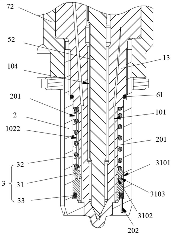
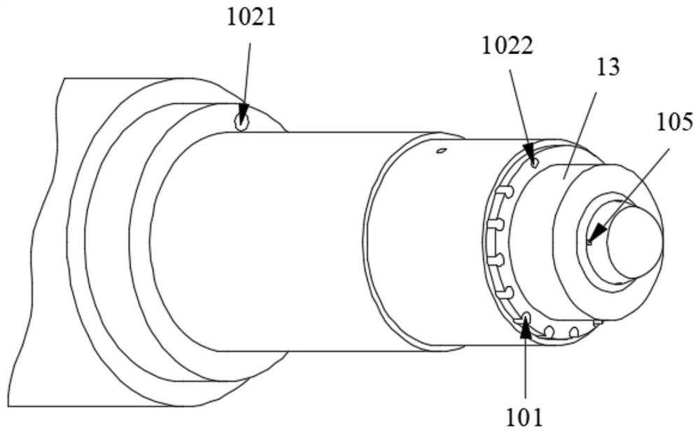
The invention relates to the technical field of dual fuel injectors, and discloses a dual fuel injector with isolation grooves and an injection method thereof. The dual-fuel injector with isolation groove includes: a valve body, which is provided with an air intake passage, an oil control inlet passage and an oil control return passage; a nozzle sleeve, which is detachably connected with the valve body and defines a pressure regulating cavity; The pressure regulating assembly is located in the pressure regulating chamber. The pressure regulating assembly includes a nozzle coupling sleeve, which is respectively assembled with the valve body and the nozzle sleeve. The nozzle coupling sleeve is provided with a first isolation groove, a second isolation groove and an oil guide hole. , the second isolation groove communicates with the oil control inlet passage, and when the pressure regulating component abuts against the end of the nozzle sleeve, the air injection hole is isolated from the air intake passage; the oil control valve is arranged on the oil control return passage. The dual-fuel injector with isolation grooves disclosed in the present invention increases the smoothness of the movement of the pressure-regulating assembly, reduces the probability of the pressure-regulating assembly being stuck, reduces the failure rate of the dual-fuel injector, and prolongs the life of the dual-fuel injector. service life.

Description

technical field [0001] The invention relates to the technical field of dual fuel injectors with isolation grooves, in particular to a dual fuel injector with isolation grooves and an injection method thereof. Background technique [0002] The existing dual-fuel injector is generally an injection valve integrating combustible gas and combustible fuel liquid, which can inject combustible fuel liquid or combustible gas into the combustion chamber. Due to the influence of its own structure, most existing dual-fuel injectors have The problem of poor injection effect and short service life, for example, high-temperature carbon deposits will be formed in the regulating oil due to friction and excessive temperature of the valve body, nozzle sleeve and nozzle coupling sleeve, which often occurs during the axial movement of the pressure regulating component Sticking increases the failure rate of dual fuel injection, reduces the injection effect of dual fuel injectors, and shortens the...

Claims


Application Information

Patent Timeline
Patent Type & Authority Patents(China)
IPC IPC(8): F02M43/04F02M63/00
CPCF02M43/04F02M63/00F02M63/0012
Inventor 高广新杨中伟张建刚朱明健朱君亮汪祥本张礼林夏少华宋国民黄成海
Owner FAW JIEFANG AUTOMOTIVE CO
Learn More