Automotive limiting device with adjustable limiting force

A limiting device and limiting technology, which are applied to the fastening devices of wing sashes, building fastening devices, buildings, etc., can solve the problems of rubber spring deformation fatigue, cumbersome maintenance procedures, door damage, etc., and achieve good use effects. , Simple structure, low cost effect

Active Publication Date: 2020-03-24
玉环县兴发动力有限公司
View PDF5 Cites 0 Cited by
  • Summary
  • Abstract
  • Description
  • Claims
  • Application Information

AI Technical Summary

Problems solved by technology

[0003] However, after the rubber spring door stopper has been in operation for a period of time, due to the deformation and fatigue of the internal rubber spring, the limit torque will decrease rapidly. It is necessary to disassemble the door and replace the rubber spring in the door to restore the limit The limit force of the stopper; the maintenance process is cumbersome and the maintenance cost is high; repeated disassembly of the door will cause certain damage to the door
[0004] In view of the disadvantages of the above-mentioned rubber spring door stopper, such as the rapid reduction of the limit torque caused by the fatigue of the internal rubber spring, and the cumbersome process of replacing the stopper, it is necessary to design a rubber spring that can be adjusted under the condition of internal rubber spring fatigue. The elastic force and then restore its limiting force to keep the limiter continuously and effectively limit the limit device for the door

Method used


Image

  • Automotive limiting device with adjustable limiting force
  • Automotive limiting device with adjustable limiting force
  • Automotive limiting device with adjustable limiting force

Examples


Embodiment Construction

[0033] The accompanying drawings are all schematic diagrams of the implementation of the present invention, so as to understand the principle of structural operation. The specific product structure and proportional size can be determined according to the use environment and conventional technology.

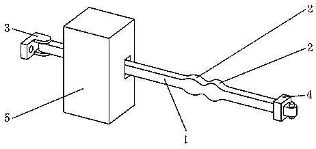
[0034] Such as figure 1 As shown, it includes a limit arm 1, a mounting seat 3, a buffer block 4, and a limit box mechanism 5, wherein one end of the limit arm 1 is fixed on the car body near the hinged part of the car door through the mounting seat 3 hinged therewith, The other end of the limit arm 1 passes through the limit box mechanism 5 fixed in the car door; the upper and lower surfaces of the limit arm 1 have two limit projections A2 that cooperate with the limit box mechanism 5, and the limit The limit protrusion A2 on the upper and lower surfaces of the arm 1 is symmetrical up and down; the end of the limit arm 1 located in the door is equipped with a buffer block 4 that...


PUM


Abstract

The invention belongs to the field of automotive door limiting devices, and particularly relates to an automotive limiting device with adjustable limiting force. The automotive limiting device with the adjustable limiting force comprises a limiting arm, an installation base, a buffering block and a limiting box mechanism. One end of the limiting arm is fixed to the portion nearby the hinge joint of an automobile body and an automotive door through the installation base which is hinged with the limiting arm, and the other end of the limiting arm passes through the limiting box mechanism which is fixedly installed inside the automotive door. Two racks which alternately move drive corresponding wedge blocks B to stagger relative to corresponding wedge blocks A along the inclined planes of thecorresponding wedge blocks A, the wedge blocks A can conduct vertical movement in the direction of the limiting arm, the moving wedge blocks A further compress corresponding telescopic rods, pressuresprings in the telescopic rods can be further compressed and store energy, and therefore the adjustment of the compression amount of each pressure spring which has the deformation fatigue is achieved, then the force of the extrusion, conducted on the limiting arm through press wheels, of the pressure springs is guaranteed, and the limiting effect of the automotive door limiting device on the opening degree of the automotive door is continuously and effectively achieved.

Description

technical field [0001] The invention belongs to the field of car door stoppers, in particular to a car door stopper with adjustable stop force. Background technique [0002] Cars are becoming more and more common in people's lives. Almost every family has their own car. With the development of the automobile industry, there have been many products for people to use cars better, such as door stoppers; they are currently widely used The special rubber spring type door stopper is fastened on the vehicle body through a mounting bolt, and the limit box is fastened on the car door through two mounting screws. When the door is opened, the limit box will move along the limit arm. Because there are different structures on the limit arm, the elastic rubber blocks will have different elastic deformations, so that people need to use different forces to close the door when opening the door. At each limit position point, it can play a limit effect on the car door. [0003] However, afte...

Claims


Application Information

Patent Timeline
Patent Type & Authority Applications(China)
IPC IPC(8): E05C17/22
CPCE05C17/28
Inventor 林晓燕张兴满
Owner 玉环县兴发动力有限公司
Why Eureka
Try Eureka