Hydraulic control system of luffing crane

A hydraulic control system and crane technology, applied in the field of hydraulic control, can solve problems affecting the normal operation, shutdown, and overload of the luffing crane

Active Publication Date: 2020-04-14
WUHAN MARINE MACHINERY PLANT
View PDF8 Cites 0 Cited by
  • Summary
  • Abstract
  • Description
  • Claims
  • Application Information

AI Technical Summary

Problems solved by technology

The lifting action and the luffing action of the luffing crane can also be carried out at the same time. When the lifting action and the luffing action are performed at the same time, if the lifting hydraulic pump and the luffing hydraulic pump are both working in a state of high power, it may The total power of the luffing crane exceeds the allowable maximum total power, which causes the luffing crane to be overloaded and shut down, affecting the normal operation of the luffing crane

Method used


Image

  • Hydraulic control system of luffing crane

Examples


Embodiment Construction

[0018] In order to make the object, technical solution and advantages of the present invention clearer, the implementation manner of the present invention will be further described in detail below in conjunction with the accompanying drawings.

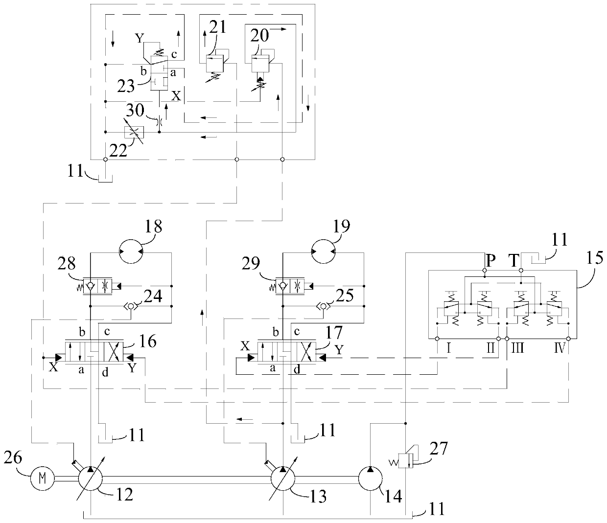
[0019] figure 1 It is a schematic diagram of a hydraulic control system of a luffing crane provided by an embodiment of the present invention. Such as figure 1 As shown, the hydraulic control system of the luffing crane includes a fuel tank 11, a lifting hydraulic pump 12, a luffing hydraulic pump 13, a control pump 14, a hydraulic control handle 15, a lifting proportional directional valve 16, and a luffing proportional directional valve 17 , Lifting motor 18, luffing motor 19, sequence valve 20, first overflow valve 21, speed regulating valve 22 and hydraulic control reversing valve 23.

[0020] The oil inlet of the lifting hydraulic pump 12 communicates with the oil tank 11, the oil outlet of the lifting hydraulic pump 12 communic...


PUM


Abstract

The invention discloses a hydraulic control system for a luffing crane, belonging to the field of hydraulic control. The hydraulic control system comprises an oil tank, a lifting hydraulic pump, a luffing hydraulic pump, a control pump, a hydraulic control handle, a lifting proportional directional valve, a luffing proportional directional valve, a lifting motor, a luffing motor, a sequence valve,a first overflow valve, a speed regulating valve and a hydraulic operated reversing valve; when the pressure of a first oil port of the luffing proportional directional valve reaches the threshold value of the sequence valve, the sequence valve is turned on, so that the hydraulic operated reversing valve is located in the right position. If oil is controlled to come out from a third oil outlet ofthe hydraulic control handle at present to cause the pressure of a first control port of the lifting proportional directional valve to reach the threshold valve of the first overflow valve, the pressure oil can enter the oil tank through the hydraulic operated reversing valve, so that the pressure of the first control port of the lifting proportional directional valve is not further increased, and thus, the luffing crane is prevented from being overloaded when lifting and luffing are simultaneously performed.

Description

technical field [0001] The invention relates to the field of hydraulic control, in particular to a hydraulic control system of a luffing crane. Background technique [0002] The luffing crane can carry out two actions of lifting and luffing. The lifting action is powered by the lifting hydraulic pump, and the luffing is powered by the luffing hydraulic pump. The lifting hydraulic pump and the luffing hydraulic pump are independent of each other. . [0003] The lifting action and luffing action of the luffing crane can be carried out separately. When lifting or luffing alone, the total power of the luffing crane is the power of the lifting hydraulic pump or the luffing hydraulic pump. The luffing crane can work normally if the maximum total power allowed is exceeded. The lifting action and the luffing action of the luffing crane can also be carried out at the same time. When the lifting action and the luffing action are performed at the same time, if the lifting hydraulic p...

Claims


Application Information

Patent Timeline
Patent Type & Authority Patents(China)
IPC IPC(8): F15B11/16F15B11/17F15B11/04B66C13/20B66C23/82
CPCB66C13/20B66C23/82F15B11/003F15B11/04F15B11/16F15B11/17F15B2211/20546F15B2211/30515F15B2211/30525F15B2211/71F15B2211/755F15B2211/7653
Inventor 汤波叶建方敏
Owner WUHAN MARINE MACHINERY PLANT
Why Eureka
Try Eureka