
A vr image transmission method

A transmission method and image technology, which is applied in the field of image transmission, can solve the problems of reducing the amount of image transmission data, freezing, etc., and achieve the effects of avoiding faults, improving viewing effects, and reasonable pictures

Active Publication Date: 2021-04-27
东方梦幻虚拟现实科技有限公司
View PDF4 Cites 0 Cited by
  • Summary
  • Abstract
  • Description
  • Claims
  • Application Information

AI Technical Summary

Problems solved by technology

[0002] In the prior art, the image transmission of virtual reality movies is usually by converting the flat image into a three-dimensional image, so that the viewer can see the three-dimensional three-dimensional movie through the VR helmet, but the image of the movie is generally a panoramic image, and the pixel It can reach 4K. In the process of such a large-capacity transmission, it is very likely that the phenomenon of stuttering will occur. Therefore, we have adopted a method that can not only allow the viewer to see the area they want to watch, but also reduce the amount of data transmitted by the picture. This way, the image in the visible area of ​​the viewer is clear, and the image in the non-visible area is blurred, but after the image is transmitted to the VR helmet in this way, the blurring generated after the clear image and compression There may be gaps between images, so we need to make the picture more reasonable and optimized to improve the user's viewing experience

Method used


Image

  • A vr image transmission method
  • A vr image transmission method
  • A vr image transmission method

Examples


Embodiment 1

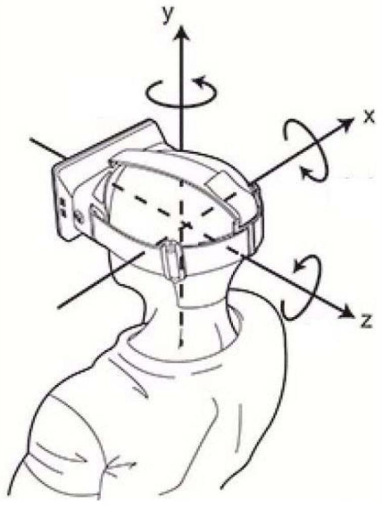
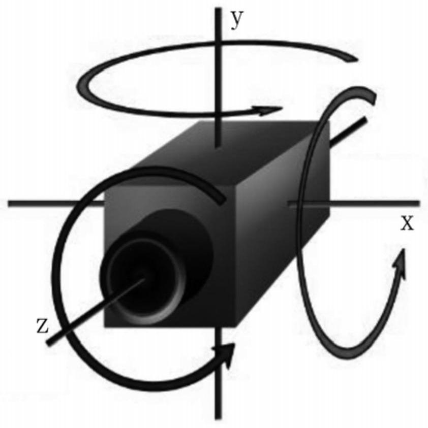
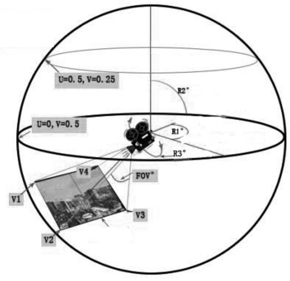
[0036] In order to solve the above problems, the present application provides a VR image transmission system, including a VR computer, a VR helmet and a positioning sensor; the VR computer is used to establish a virtual space, and the VR computer stores the reference position of the VR helmet and when the VR helmet When at the reference position, the reference position of the viewing cone area that the person wearing the helmet can watch in the virtual space; the positioning sensor is fixed on the VR helmet for sensing the spatial position of the VR helmet; the VR computer and the positioning sensor Communication connection, so that the VR computer can obtain the change of the position of the VR helmet through the positioning sensor; The VR computer is connected to the VR helmet in communication; The VR helmet is provided with a field of view, and the field of view of the VR helmet It is the angle formed by the two lines of sight in the largest range that can be seen by a singl...

Embodiment 2

[0078] Due to the image formed in the first embodiment above, there may be a gap between the clear image in the first visible area and the blurred image generated after compression. Therefore, in order to make the picture more reasonable and optimized, we can adopt a method:

[0079] Such as Figure 5 As shown, the second visible area 3 including the first visible area 2 is set, the second position of the second visible area 3 on the first plane image is recorded, and the second visible area in the first plane image 1 is The area other than area 3 is set as background area 6;

[0080] The first plane image 1 is compressed under the condition that the image size is constant to obtain the first compressed image; if the first plane image is M pixels, the first compressed image pixels obtained after compression are M / Q (Q>1 ); wherein, Q is a real number greater than 1.

[0081] Set HD area 4 inside first visible area 2, described HD area is in the center of second visible area ...

Embodiment 3

[0087] According to the settings in Example 2, we can also add a module with virtual shooting function on the VR computer, so that the VR computer can shoot images in the movie. Through this setting, we can get another way to render the background:

[0088] According to Embodiment 2, it can be seen that in order to make the final picture seen by the wearer more reasonable, the image in the first visible area in the final output composite image is a clear image, and the image outside the first visible area has a gradually blurred image. Therefore, this effect can be realized by shooting an image with depth of field on the first plane image. When shooting an image with depth of field, there is an allowable circle of confusion in front of and behind the focus of the lens, and the distance between the two circles of confusion is Depth of field, set to m, where the distance from the focal point of the lens to the near-permissible circle of confusion is set as the foreground depth ΔL...


PUM


Abstract

This application provides a VR image transmission method, the steps are: after the VR computer sends the first plane image of the movie to the VR helmet, the VR computer obtains the first visible area that the wearer of the VR helmet can see on the first plane image ; Set the second visible area including the first visible area, record the second position of the second visible area on the first plane image, and set the area outside the second visible area in the first plane image as Background area; set the edge of the second visible area as the first edge, and the edge of the high-definition area as the second edge, then the image is set to be gradually blurred from the second edge to the first edge; the first plane image is placed in its image Compression is performed under the condition that the size remains unchanged to obtain a first compressed image; the image in the second visible area is overlaid on the first compressed image at a second position, and combined to form a second composite image. This application makes the picture of the film more optimized, and improves the viewing experience of the user.

Description

technical field [0001] The present application relates to the field of image transmission, in particular to a VR image transmission method. Background technique [0002] In the prior art, the image transmission of virtual reality movies is usually by converting the flat image into a three-dimensional image, so that the viewer can see the three-dimensional three-dimensional movie through the VR helmet, but the image of the movie is generally a panoramic image, and the pixel It can reach 4K. In the process of such a large-capacity transmission, it is very likely that the phenomenon of stuttering will occur. Therefore, we have adopted a method that can not only allow the viewer to see the area they want to watch, but also reduce the amount of data transmitted by the picture. This way, the image in the visible area of ​​the viewer is clear, and the image in the non-visible area is blurred, but after the image is transmitted to the VR helmet in this way, the blurring generated af...

Claims


Application Information

Patent Timeline
Patent Type & Authority Patents(China)
IPC IPC(8): H04N13/271H04N13/344
Inventor 孟宪民李小波赵德贤
Owner 东方梦幻虚拟现实科技有限公司
Learn More