
A kind of LED light detection device

A technology of LED lamps and detection devices, applied in the direction of lamp testing, etc., can solve problems such as identification errors and burns, and achieve the effect of avoiding the risk of identification errors.

Active Publication Date: 2022-02-15
深圳市恒彩芯微光电科技有限公司
View PDF8 Cites 0 Cited by
  • Summary
  • Abstract
  • Description
  • Claims
  • Application Information

AI Technical Summary

Problems solved by technology

[0004] In view of this, the purpose of the present invention is to propose a LED lamp detection device to solve the problem that a large amount of heat will be generated when the LED lamp is turned on in the prior art. If any LED is found to be off during the test, At this time, it is easy to get burned if you take out the LED lights that do not light up or mark them. However, after the unified test is completed, to identify the LED lights that do not light up during the test, there is a technical problem with the risk of identification errors.

Method used


Image

  • A kind of LED light detection device
  • A kind of LED light detection device
  • A kind of LED light detection device

Examples


Embodiment Construction

[0022] In order to make the object, technical solution and advantages of the present invention clearer, the present invention will be described in further detail below in conjunction with specific embodiments and with reference to the accompanying drawings.

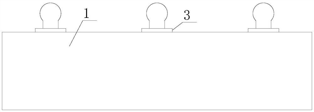
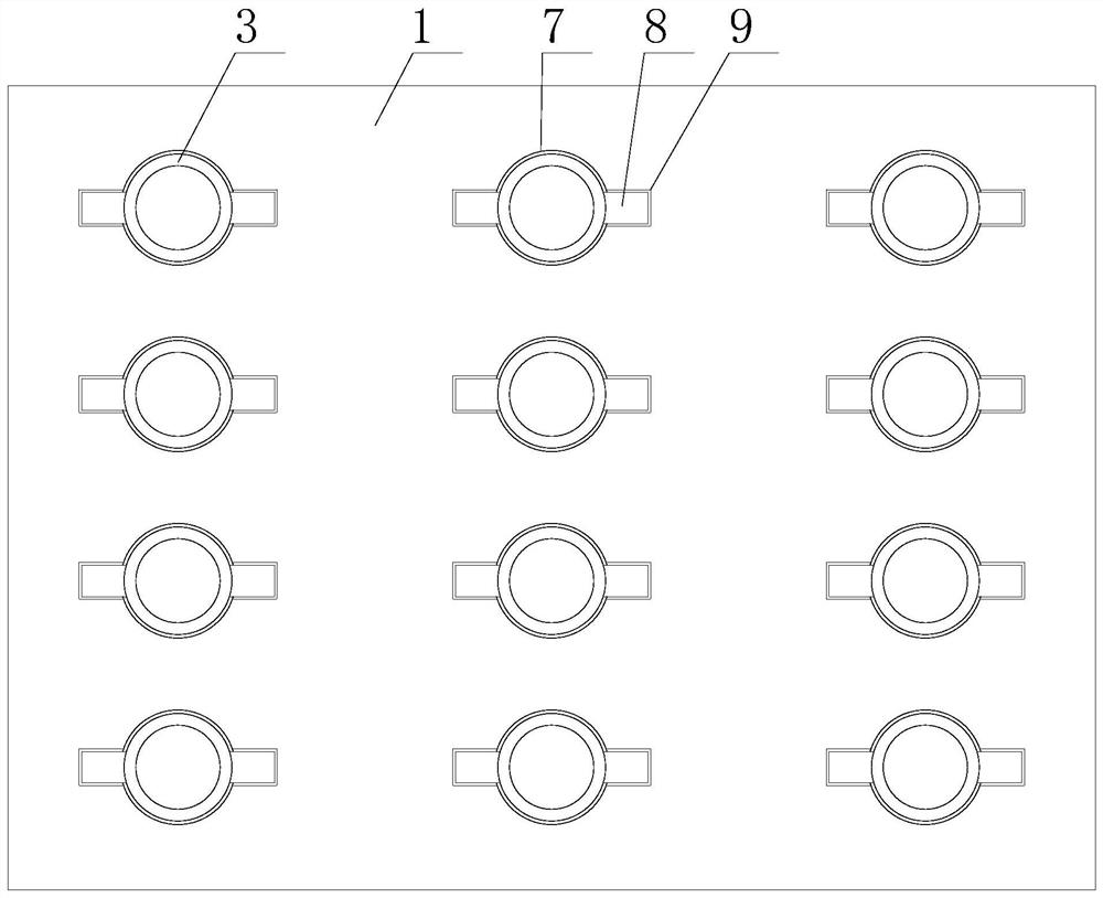
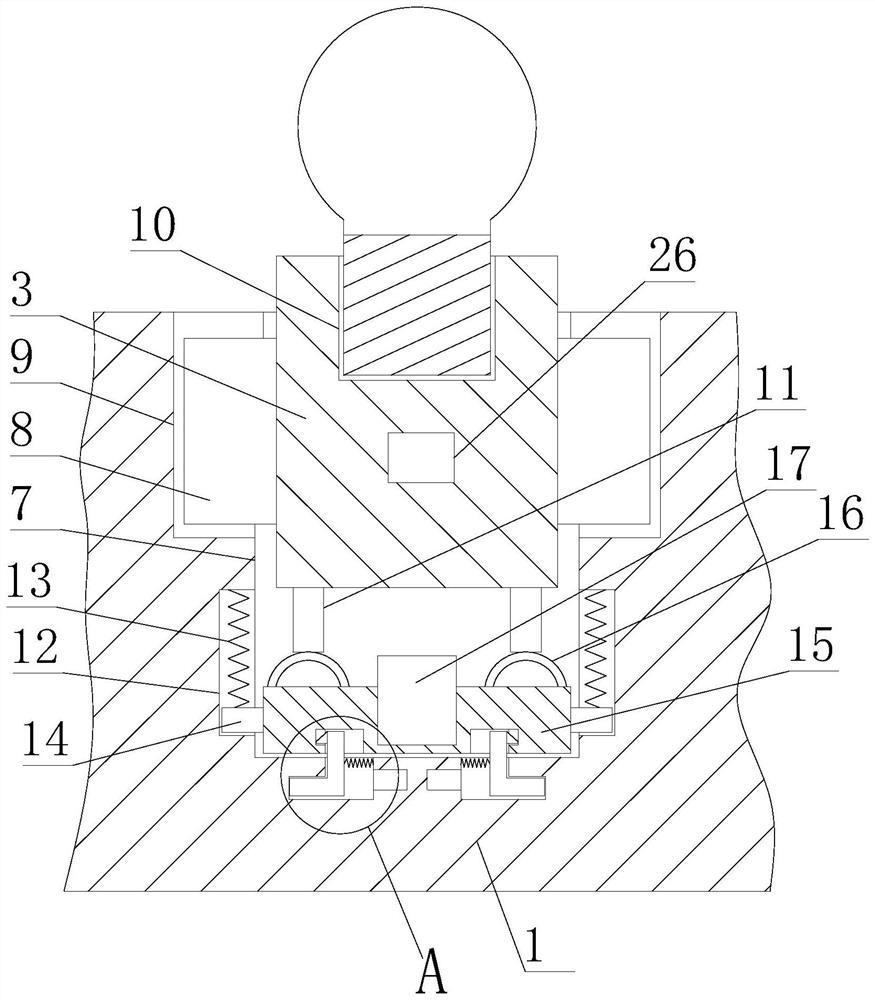
[0023] Based on the above purpose, the first aspect of the present invention proposes an embodiment of an LED lamp detection device, such as figure 1 , figure 2 and image 3 shown, including,

[0024] The workbench 1 is provided with several placement holes 7 on its upper end surface;

[0025] The support column 3 corresponding to the placement hole 7 is provided with two conductive columns 11 at its bottom, and a test hole 10 is provided on its upper end surface, and a positive electric block and a negative electric block are arranged in the test hole 10. The electric block is electrically connected to one of the conductive columns 11, and the negative electric block is electrically connected to the other conductive ...


PUM


Abstract

The invention discloses an LED lamp detection device, which relates to the field of lighting detection, comprising: a workbench, the upper end surface of which is provided with a number of placement holes; support columns corresponding to the placement holes one by one, the bottom of which is provided with two conductive columns, and Its upper end surface is provided with a test hole, and a positive block and a negative block are arranged in the test hole, the positive block is electrically connected to one of the conductive columns, and the negative block is electrically connected to the other conductive column; A voltmeter, one test end of the voltmeter is electrically connected to the positive electric block, and the other test end of the voltmeter is electrically connected to the negative electric block; the lifting mechanism is provided on the end face facing the outlet of the placement hole to be provided with a corresponding conductive column. The elastic piece; the controller, which is electrically connected with the lifting mechanism and the voltmeter, can avoid taking out the unlit LED lights or marking them during the test, causing burns, and at the same time, after the test is completed, it can pass through the height of the support column. To identify LED lights that do not light up during testing, avoiding the risk of misidentification.

Description

technical field [0001] The invention relates to the field of lighting detection, in particular to an LED lamp detection device. Background technique [0002] The LED lamp is an electroluminescent semiconductor material chip, which is cured on the bracket with silver glue or white glue, and then connected to the chip and the circuit board with silver or gold wires, and sealed with epoxy resin around it to protect the inner core wire. The role is to install the shell at last. After the factory produces the LED lamp, it needs to conduct a lighting test on the LED lamp to detect whether the LED cannot be lit and prevent unqualified products from entering the market. [0003] The applicant found that: when the LED lights are tested for lighting, a large amount of heat will be generated. If during the test, it is found that some LEDs are not bright, it is easy to get burned if you go to pick up the LED lights that are not bright or mark them. To identify the LED lights that are n...

Claims


Application Information

Patent Timeline
Patent Type & Authority Patents(China)
IPC IPC(8): G01R31/44
CPCG01R31/44
Inventor 刘玉闯
Owner 深圳市恒彩芯微光电科技有限公司
Learn More