Ultrasonic lead-acid storage battery

A lead-acid battery, ultrasonic technology, applied in the direction of lead-acid battery, lead-acid battery construction, secondary battery repair/maintenance, etc., can solve the problems of non-environmental protection, pollution of the natural environment, lead-acid battery scrapping, etc., to achieve charging and discharging performance The effect of stability, extended service life and simple maintenance

Active Publication Date: 2020-03-27
彭志军
View PDF4 Cites 9 Cited by
  • Summary
  • Abstract
  • Description
  • Claims
  • Application Information

AI Technical Summary

Problems solved by technology

In existing lead-acid batteries, lead sulfate crystals will adhere to the surface of the electrode plate after the battery has been used for a certain period of time. With the increase of lead sulfate crystals, it will hinder the contact between the electrode plate and the electrolyte, thereby affecting the lead-acid battery. Power storage performance, charge and discharge performance
Over time, the electrode plates of the lead-acid battery will not be completely worn out, and the lead-acid battery will no longer be able to store electricity and charge and discharge.
In daily production and operation activities, people have to replace new lead-acid batteries frequently, which not only greatly increases the cost of people’s production and operation activities, but also causes a large number of lead-acid batteries to be scrapped, polluting the natural environment, and is not environmentally friendly.
At this stage, people have not found an extremely effective technical means to prevent lead sulfate crystals from adhering to the electrode plates, so as to prolong the service life of lead-acid batteries and reduce the number of scrapped lead-acid batteries

Method used


Image

  • Ultrasonic lead-acid storage battery
  • Ultrasonic lead-acid storage battery
  • Ultrasonic lead-acid storage battery

Examples


Embodiment Construction

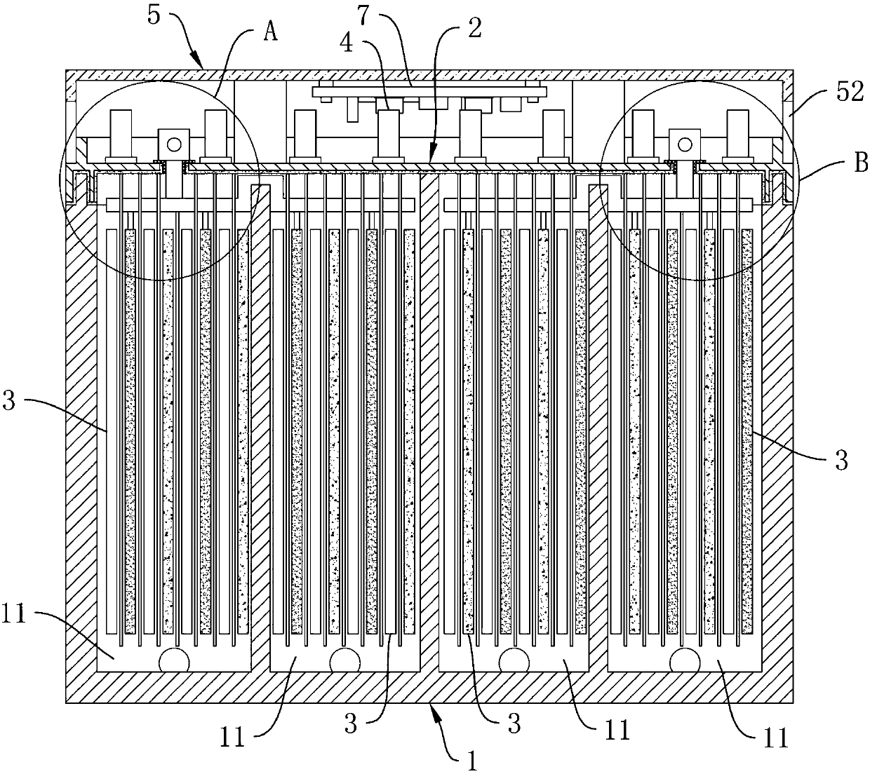
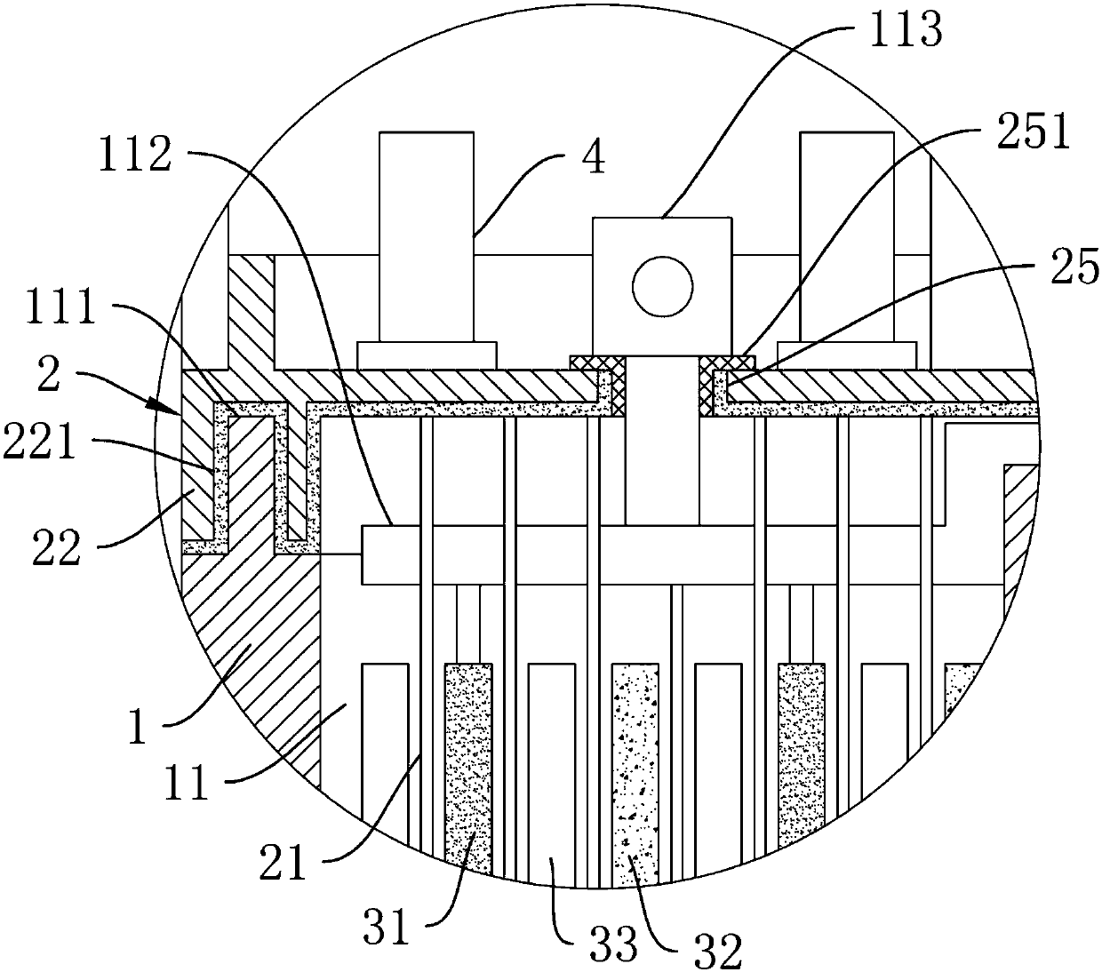
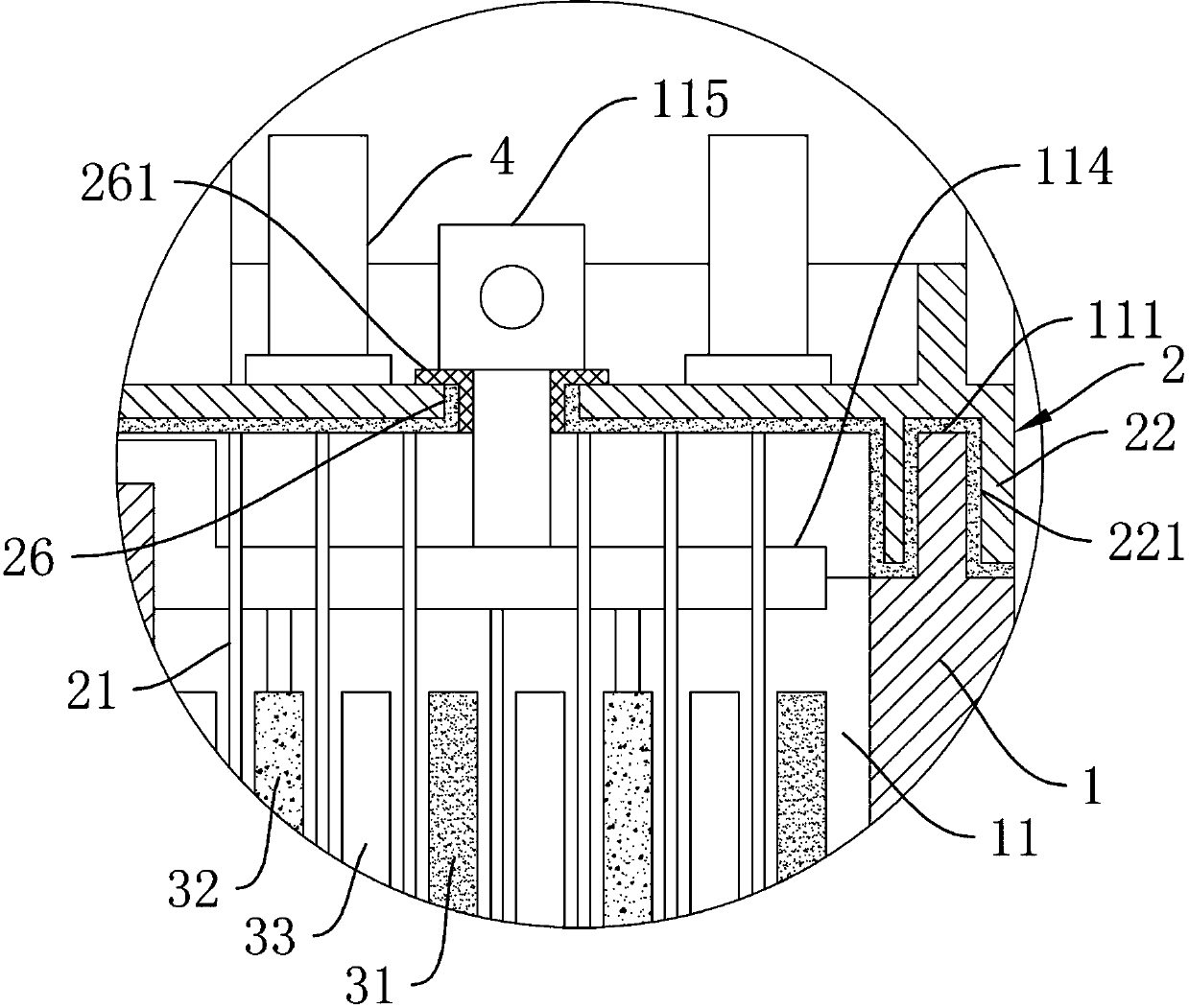
[0025] Such as figure 1 As shown, a kind of ultrasonic lead-acid storage battery of the present invention comprises battery casing 1, battery cover 2, cluster group 3, at least one ultrasonic transducer 4, wherein, as Figure 4 As shown, the top of the battery case 1 is provided with an accommodating chamber 11, and the outer wall of the battery case 1 is provided with a drain port 12 penetrating to the accommodating chamber 11, and a sealing plug 13 is provided in the drain port 12; Figure 1 to Figure 4 As shown, the bottom of the battery cover 2 is provided with some insulating and corrosion-resistant vibrating bars 21; Figure 1 to Figure 4 As shown, the cluster group 3 includes a number of positive plates 31, a number of negative plates 32, and a number of separators 33, each positive plate 31 and negative plate 32 are stacked in an interlaced manner, and each separator 33 is respectively arranged on the positive plate 31 and the negative plate. between the plates 32; th...


PUM


Abstract

The invention relates to an ultrasonic lead-acid storage battery. The battery comprises a battery shell, a battery cover, a cluster group and at least one ultrasonic transducer, an accommodating cavity is formed in the top of the battery shell; a liquid outlet penetrating to the accommodating cavity is formed in the outer wall of the battery shell; a sealing plug is arranged in the liquid outlet;a plurality of insulating corrosion-resistant vibration strips are arranged at the bottom of the battery cover; the cluster group comprises a plurality of positive plates, a plurality of negative plates and a plurality of clapboards; the positive plates and the negative plates are stacked together in a staggered mode, the partition plates are arranged between the positive plates and the negative plates respectively, the cluster set is arranged in the containing cavity, the vibration strips are inserted between the positive plates and the partition plates and between the negative plates and thepartition plates respectively, and the ultrasonic transducer is arranged on the top face of the battery cover. Lead sulfate crystals on the surface of the battery plate are prevented by utilizing high-frequency ultrasonic oscillation, so that the battery plate is in full and comprehensive contact with an electrolyte, the attenuation of the electric power storage performance of the storage batterycan be greatly relieved, and the service life of the storage battery is prolonged.

Description

technical field [0001] The invention relates to the technical field of accumulators, in particular to a lead-acid accumulator. Background technique [0002] A lead-acid battery is a battery whose electrodes are mainly made of lead and its oxides, and the electrolyte is a sulfuric acid solution. In the discharge state of the lead-acid battery, the main component of the positive electrode is lead dioxide, and the main component of the negative electrode is lead; in the charging state, the main component of the positive and negative electrodes is lead sulfate. In existing lead-acid batteries, lead sulfate crystals will adhere to the surface of the electrode plate after the battery has been used for a certain period of time. With the increase of lead sulfate crystals, it will hinder the contact between the electrode plate and the electrolyte, thereby affecting the lead-acid battery. Storage performance, charge and discharge performance. Over time, the electrode plates of the l...

Claims


Application Information

Patent Timeline
Patent Type & Authority Applications(China)
IPC IPC(8): H01M10/12H01M10/42
CPCH01M10/12H01M10/4242Y02E60/10Y02P70/50
Inventor 彭志军
Owner 彭志军
Why Eureka
Try Eureka