Al technical title is built by PatSnap Al team. It summarizes the technical point description of the patent document.
A kind of technology of chemical anchor bolt and puncher, applied in the field of puncher
Active Publication Date: 2020-03-31
NANJING YUZHI INTELLIGENT TECH CO LTD
View PDF6 Cites 4 Cited by
Summary
Abstract
Description
Claims
Application Information
AI Technical Summary
This helps you quickly interpret patents by identifying the three key elements:
Problems solved by technology
Method used
Benefits of technology
Problems solved by technology
[0005] In order to overcome the shortcoming of needing to manually carry the drilling machine to complete the drilling, and then manually clean the dust in the hole, the technical pro
Method used
Image
Click on the blue label to locate the original text in one second.
Reading with bidirectional positioning of images and text.
Examples
Embodiment 1
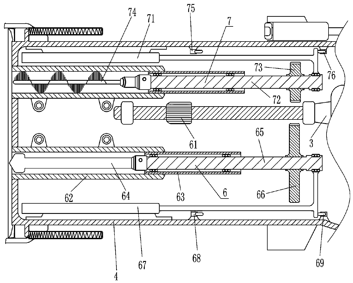
[0025] A chemical anchor bolt dustproof hole puncher, such as Figure 1-2 As shown, it includes a handle 1, a driving motor 3, a mounting plate 4, a punching mechanism 6 and a hole cleaning mechanism 7, the top of the handle 1 is provided with a mounting plate 4, the right part of the mounting plate 4 is equipped with a driving motor 3, and the left side of the mounting plate 4 The upper part of the side is provided with a start key 2, the bottom left part of the mounting plate 4 is provided with a punching mechanism 6, the punching mechanism 6 is used to install and punch holes, and the upper left part of the mounting plate 4 is provided with a hole cleaning mechanism 7, and the hole cleaning mechanism 7 is used for Clean the inside of the hole.
[0026] The punching mechanism 6 includes a first gear 61, a guide cylinder 62, a conduit 63, a drill bit 64, a first transmission shaft 65, a second gear 66, a first electric push rod 67, a first travel switch 68, and a second trave...
Embodiment 2
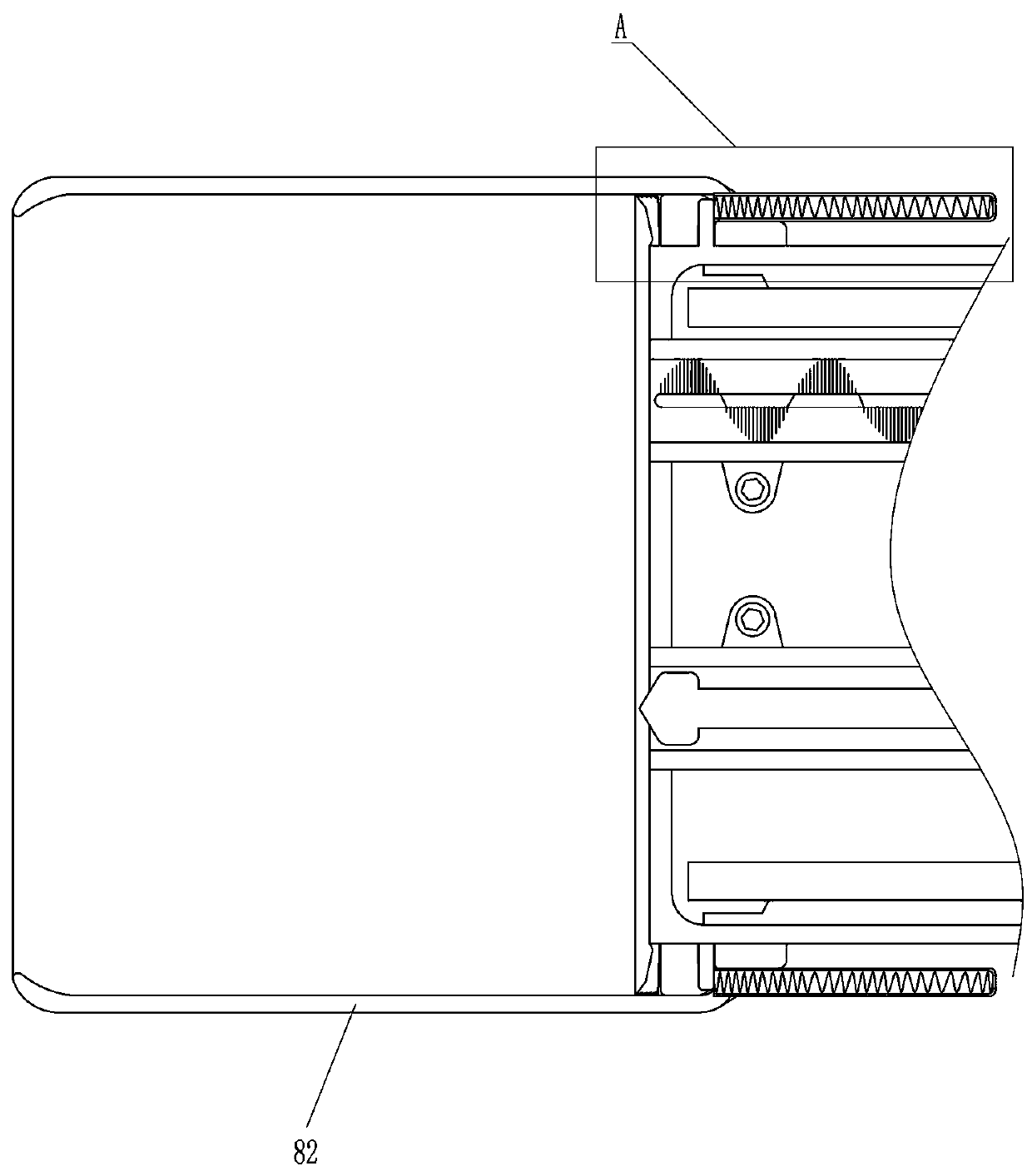
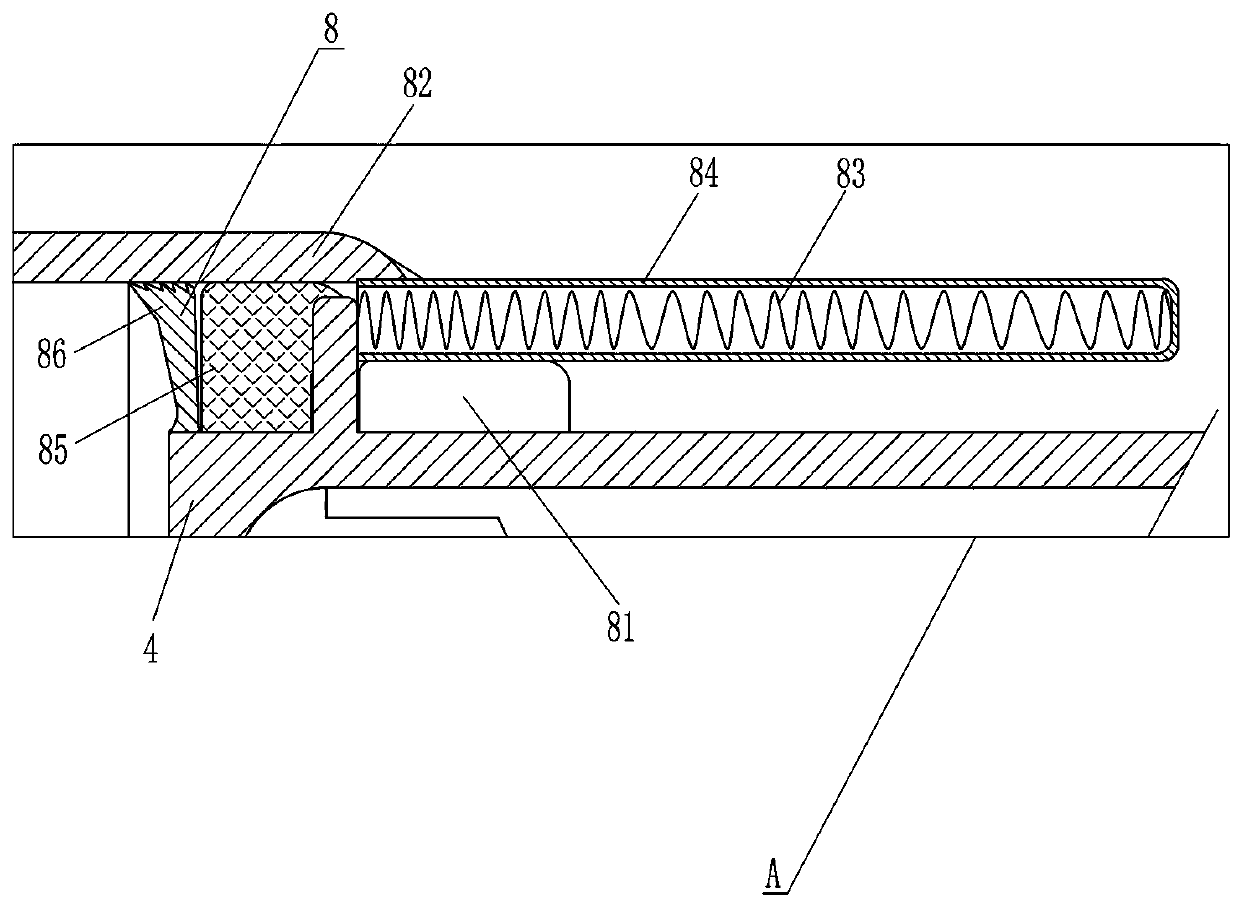
[0033] On the basis of Example 1, such as Figure 3-6 Shown, also include dustproof mechanism 8, dustproof mechanism 8 includes sliding ring 81, dustproof cover 82, spring 83, protection tube 84, sponge ring 85 and dustproof pad 86, mounting plate 4 left parts are covered with sliding Ring 81, the upper and lower sides of sliding ring 81 are all provided with protective tube 84, and spring 83 is all provided with between the inner right end of protective tube 84 and mounting plate 4, and the left part of mounting plate 4 is covered with dust cover 82, and dust cover 82 The upper, lower, and right sides are fixedly connected to the outer sides of the protection tubes 84 on the upper and lower sides, and the outside of the left part of the mounting plate 4 in the dust cover 82 is provided with a sponge ring 85 and a dust pad 86, and the sponge ring 85 is located at the dust pad 86 Right.
PUM
Abstract
The invention relates to a puncher, and particularly relates to a dustproof puncher for a chemical anchor bolt. The technical problem to be solved is how to provide a chemical anchor bolt dustproof puncher which is capable of automatically punching, automatically cleaning the interior of a hole and playing an effect of dust prevention. The dustproof puncher for the chemical anchor bolt comprises ahandle, a mounting plate and the like, wherein the mounting plate is arranged at top end of the handle. According to the invention, the dustproof puncher can achieve the purposes of automatic punching and hole interior cleaning through the cooperation of a punching mechanism and a hole cleaning mechanism, and can play the effect of dust prevention through a dustproof mechanism, chippings and dustgenerated during punching can be prevented from entering a protective pipe to affect movement of a drill bit through a sponge ring and a dustproof pad, and the moving position of a protective cover can be adjusted by rotating an adjusting screw clockwise and anticlockwise by a worker.
Description
technical field [0001] The invention relates to a hole puncher, in particular to a chemical anchor bolt dustproof hole puncher. Background technique [0002] Chemical anchor is a new type of fastening material, which is composed of chemical agents and metal rods. It can be used for the installation of post-embedded parts in various curtain walls and marble dry-hanging construction, and can also be used for equipment installation, road and bridge guardrail installation, building reinforcement and transformation, etc. Because the chemical reagents contained in the glass tube are flammable and explosive, the manufacturer must obtain the approval of the relevant state department before production. The entire production process requires strict safety measures and must use an assembly line completely isolated from the staff. If it is done manually, it not only violates the relevant regulations of the country, but also is very dangerous. [0003] The chemical anchor bolt is a new...
Claims
Application Information
Patent Timeline
Application Date:The date an application was filed.
Publication Date:The date a patent or application was officially published.
First Publication Date:The earliest publication date of a patent with the same application number.
Issue Date:Publication date of the patent grant document.
PCT Entry Date:The Entry date of PCT National Phase.
Estimated Expiry Date:The statutory expiry date of a patent right according to the Patent Law, and it is the longest term of protection that the patent right can achieve without the termination of the patent right due to other reasons(Term extension factor has been taken into account ).
Invalid Date:Actual expiry date is based on effective date or publication date of legal transaction data of invalid patent.